Gantry shear is a heavy-duty industrial machine used for cutting large metal plates, sheets, and structural components. It features a gantry-style frame with a moving upper blade that shears material against a fixed lower blade. Commonly employed in metal fabrication, steel processing, and recycling operations, gantry shears are valued for their high precision, powerful cutting capacity, and ability to handle sizable workpieces. Safe and efficient operation relies on strict adherence to standardized procedures and preventive safety measures.
1. Safe Operating Procedures During Operation
Standardized Material Loading
When loading materials using overhead cranes, lifting devices, or loading trolleys, all lifting safety regulations must be strictly followed to ensure stable and secure hoisting.
During manual loading, personnel must coordinate and use appropriate tools—such as magnetic chucks or hooks—to prevent cuts and injuries. Never place hands or any part of the body under the upper blade or in areas where material may shift or tip.
Precise Positioning
Use the equipment’s scales, stop gauges, or CNC programming system to accurately set cutting dimensions.
When adjusting material position, always use proper tools (e.g., pry bars). Do not push or support material directly with hands.
Safe Start-up and Monitoring
Operators must stand in a safe location, typically in front of the control panel, with no body parts entering the cutting zone.
Initiate the cutting cycle only after confirming that all personnel have cleared the danger area.
Maintain full attention during cutting and continuously monitor material behavior. If misalignment, jamming, unusual noise, or vibration occurs, immediately press the emergency stop button.
Safe Material Discharge and Stacking
After shearing, wait for the machine to come to a complete stop, the upper blade to return to its highest position, and the clamping device to fully release before removing the workpiece.
Sort finished workpieces and scrap edges, placing them in designated racks or containers. Stack materials neatly and securely to prevent slipping or falling. Remove scrap promptly.
Prohibited Behaviors (Highest Priority)
Do not shear material that exceeds the equipment’s rated capacity in thickness or strength.
Do not shear multiple pieces of different specifications or materials simultaneously.
Never place hands, arms, or tools between the upper and lower blades, under the clamping device, or near any moving parts.
Do not perform maintenance, cleaning, adjustment, or measurement while the machine is operating.
Do not remove, bypass, or disable any safety guards or devices.
Do not leave the operating station unattended while the equipment is running.
2. Post-Operation and Maintenance Safety
Standardized Shutdown
After operation, stop the machine in a safe position (upper blade fully raised), disconnect the main power supply, and engage the emergency stop button.
Thorough Cleaning
Remove all metal chips, waste material, and oil residue from inside and outside the equipment. Use brushes, scrapers, or other tools—never handle debris with bare hands.
Shift Handover
Accurately record equipment operating status and any abnormalities. Ensure clear communication between shifts.
Professional Maintenance
Only qualified maintenance personnel may perform daily upkeep, periodic inspections, and blade replacement
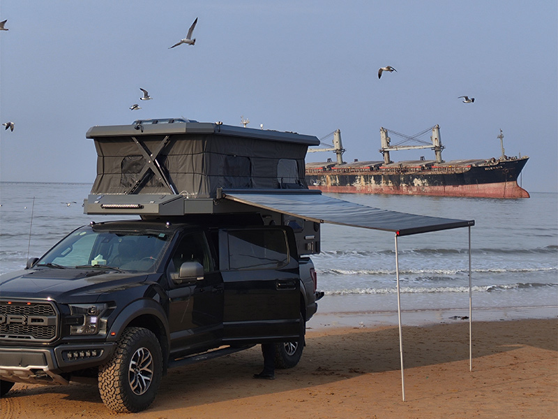
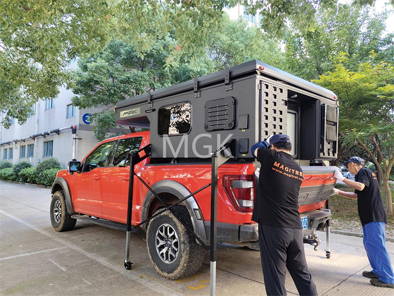
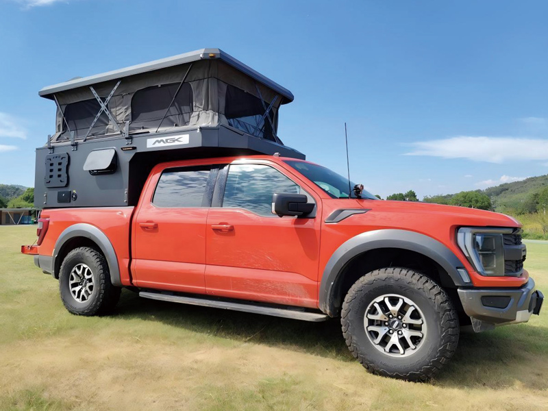
 Wide product range: Aluminum pickup truck camper, Fiberglass pickup truck camper, canopy, tent, roof car tent, RV accessories etc.
 MOQ: just 1 set.
 To receive the full catalog & dealer price list, come and send inquiries. One step ahead of time, you can seize the market first!


 Wide product range: Aluminum pickup truck camper, Fiberglass pickup truck camper, canopy, tent, roof car tent, RV accessories etc.
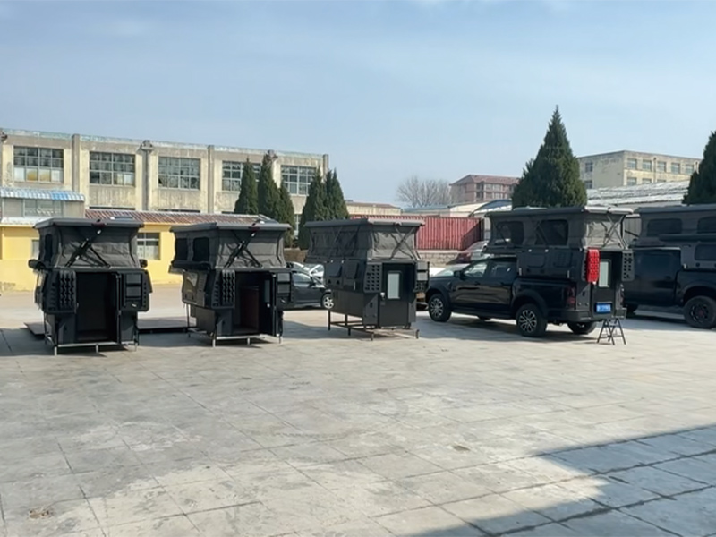
 Expandable Cabin Design: Innovative side-extension module increases interior space by up to 35%, offering more room for rest, storage, and family trips.
 Wide product range:
  MOQ: just 1 set.
