Do you know what a tensile testing machine is? Let's uncover its mysteries together.
1. What is a tensile testing machine?
A tensile testing machine, also known as a universal testing machine, is like a doctor that gives materials a comprehensive “checkup.” It is mainly used to measure the mechanical properties of various materials, such as plastics, metals, rubber, and textiles. By applying forces such as tensile, compressive, bending, shear, peel, and tear forces to these materials, it can precisely measure important performance indicators such as strength, toughness, and elastic modulus.
In terms of working principle, a tensile testing machine primarily relies on Hooke’s Law and strain measurement principles. Hooke’s Law states that within the elastic range, the force applied to a material is directly proportional to the deformation it undergoes. The strain measurement principle involves calculating the material's various mechanical properties by measuring the minute deformation of the material under force. When a material sample is secured to the tensile testing machine and the force is gradually increased, the sensors on the machine precisely record the force applied to the material and the resulting deformation, thereby determining the material's performance parameters.
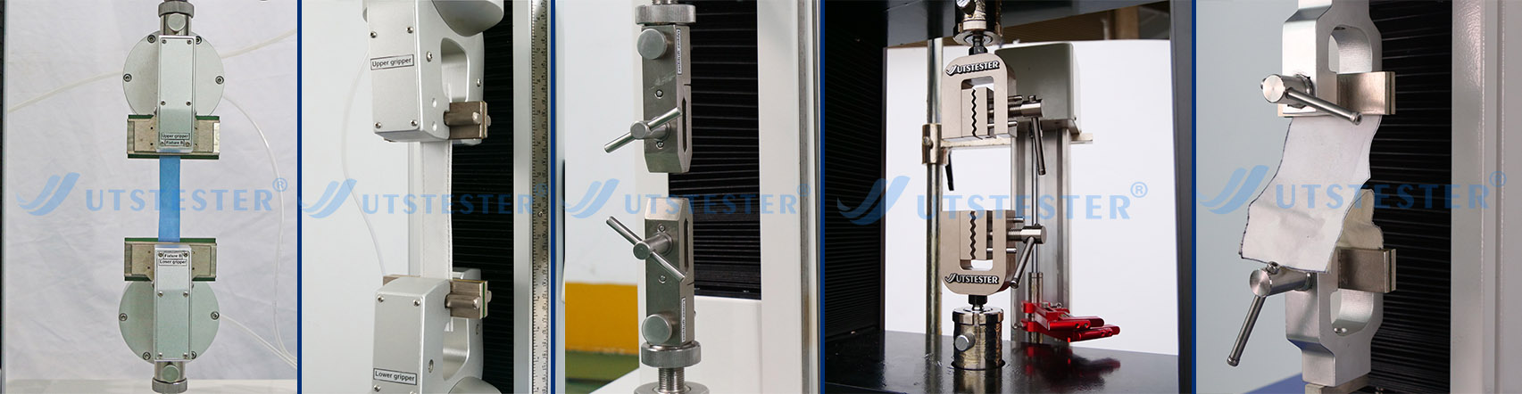
A tensile testing machine primarily consists of several key components. First is the drive system, which transmits the motor's power to the loading system. The loading system is responsible for applying force to the material and can precisely control the magnitude and direction of the force applied to the material according to different test requirements. The measurement system uses various sensors, such as force sensors and displacement sensors, to monitor the force applied to the material and the resulting deformation in real time. The control system can precisely control the entire testing process according to pre-set programs, ensuring the accuracy and reliability of the test results.
2I. Classification of Tensile Testing Machines
There are numerous types of tensile testing machines, which can be classified according to different standards.
Based on the level of automation, we can classify them into pointer-type tensile testing machines, digital display tensile testing machines, and computer system tensile testing machines.
Based on the type of control system, they can be categorized into variable frequency system tensile testing machines, servo system tensile testing machines, and other drive type tensile testing machines.
Based on industry and functional characteristics, they can be categorized into metal tensile testing machines, rubber tensile testing machines, plastic tensile testing machines, textile tensile testing machines, paper tensile testing machines, and leather tensile testing machines, among others.
Additionally, they can be categorized based on test materials, temperature, application, and degree of automation. For example, based on test materials, they can be divided into tensile testing machines with metal material fixtures and non-metal material fixtures; based on test temperature, they can be divided into tensile testing machines with room temperature, high-temperature, low-temperature, and high-low temperature fixtures; based on application, they can be divided into tensile fixtures, compression fixtures, bending fixtures, and other application-specific tensile testing machines; based on automation level, they can be divided into manual, pneumatic, electric, and hydraulic fixture tensile testing machines.
3. Application Areas of Tensile Testing Machines
Tensile testing machines have widespread applications across various fields.
In the industrial sector, industries such as manufacturing, metallurgy, petroleum, chemicals, and construction materials all rely on tensile testing machines.
For example, in mechanical manufacturing, tensile testing machines can be used to test the strength and toughness of various mechanical components, ensuring product quality and reliability. In the manufacturing industry, textile factories use tensile testing machines to test the elongation rate of fabrics, ensuring that finished garments do not deform easily when worn.
In the metallurgy industry, tensile testing machines can be used to test the performance of metallic materials such as steel, providing a basis for improving metallurgical processes.
In the petroleum and chemical industries, tensile testing machines can be used to test the material properties of various pipelines, containers, and other equipment, ensuring safe operation under harsh working conditions.
In the construction materials industry, tensile testing machines can be used to test the performance of construction materials such as cement, bricks, and steel, ensuring the quality of construction projects.
In the field of scientific research, tensile testing machines are indispensable tools. Researchers can use tensile testing machines to conduct performance tests and studies on various new materials, contributing to the development of materials science.

Email: hello@utstesters.com
Direct: + 86 152 6060 5085
Tel: +86-596-7686689
Web: www.utstesters.com