After every trip, luggage inevitably bears the marks of wear—worn wheels, scratched shells, loose handles, and pilled fabric. These seemingly minor damages accumulate over time, leading to premature “retirement” of the luggage. While luggage appears to undergo only “packing and transportation” during travel, it actually endures multidimensional, high-frequency complex wear: friction on airport conveyor belts, impact during baggage handling, dragging abrasion on varied surfaces, material aging from temperature and humidity fluctuations, and even fatigue damage from repeated zipper cycles and telescoping handle movements. The core of laboratory simulation testing lies in condensing this “years of accumulated wear” into quantifiable, repeatable standard procedures. By precisely replicating real-world usage scenarios, it identifies product weaknesses early, providing scientific grounds for optimizing designs and enhancing quality.
I. Why Simulate Travel Wear in a Lab?
Many may wonder: Isn't testing luggage directly in real-world travel scenarios more realistic? In fact, field testing faces three major challenges: First, excessive duration—simulating 3-5 years of wear may require hundreds of check-in cycles and drag tests, taking months or even years and severely delaying product launch. Second, variables are uncontrollable. Significant differences in road surfaces, temperature/humidity, and handling force across trips make test results unrepeatable, hindering the establishment of consistent quality standards. Third, wear is difficult to quantify. Visual inspection can only determine “damage presence” but cannot precisely measure “wear severity,” making it hard to compare the merits of different materials and designs.
Laboratory simulation testing precisely addresses these challenges: By employing standardized equipment and fixed parameters, it accelerates years of natural wear and tear, completing equivalent testing within days or even hours. Simultaneously, it precisely quantifies wear data—such as abrasion depth, mass loss, and fatigue cycles—providing measurable metrics for product durability.
II. Core Testing Items
Luggage wear primarily occurs in four core components: fabric/shell, wheels, retractable handle, and zippers, while also being significantly influenced by environmental factors. Through targeted testing protocols, the laboratory simulates various wear scenarios one by one. Each test corresponds to real-world travel wear and tear, with clear standards and quantifiable metrics.
(1) Fabric/Shell Abrasion Testing: Simulating Long-Term Wear from Checked Baggage Handling and Friction
The fabric (soft-sided cases) or shell (hard-sided cases) is the most visibly susceptible to wear—friction on airport conveyor belts, collisions with other luggage, and scraping during ground dragging all accelerate deterioration. The laboratory primarily employs two core devices to simulate different wear types:
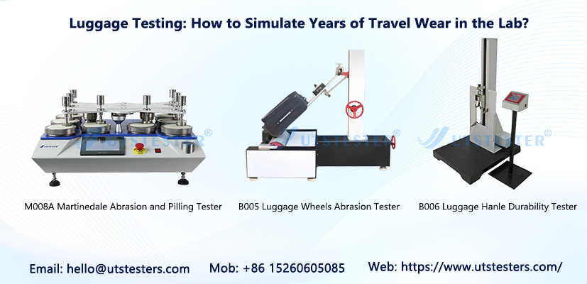
1. Martindale Abrasion Tester: Primarily for soft-shell fabrics (e.g., polyester, canvas), simulating long-term friction durability. During testing, per EN 12127 standards, samples undergo 5,000 friction cycles at 12 kPa pressure. Passing requires no yarn breakage or holes, ≤10% mass loss, and a pilling grade ≥3 in the friction area (per ISO 12945-2). Practical experience shows that standard polyester fabrics often exhibit noticeable pilling after 3,000 cycles. Manufacturers are advised to adopt high-density weaving techniques (warp/weft density ≥ 65 threads/cm²) or apply PU coatings to improve pass rates.
2. Rotary Abrasion Tester: Primarily for rigid case bodies (e.g., ABS, PC, aluminum-magnesium alloys). Following EN 16283 standards, it uses specified abrasive paper as the friction medium to apply 500 cycles of friction at a defined load of 9.8N to the sample surface. Post-test, three critical metrics must be met: no visible perforations on the surface; color difference ΔE ≤ 3.5 in the friction area; wear depth not exceeding 20% of the material thickness.
Additionally, for fabric scratch resistance, the Taber abrasion tester is employed. Following ASTM D4060 (Taber abrasion test) standards, an aluminum wheel or sandpaper wheel is used to rub the sample surface under specified load and revolutions, quantifying the material's wear resistance. For hard cases, additional drop-weight impact and static pressure tests simulate heavy-object collisions and stacking compression during shipping. Per QB/T 2155-2018 standards, hard cases must withstand 80kg static pressure testing, while plastic case surfaces must pass a 1-meter drop-ball impact test, ensuring no cracking or severe deformation occurs.
(2) Wheel Wear and Fatigue Testing: Simulating Long-Term Dragging Wear
Wheels serve as the “feet” of luggage and are among its most vulnerable components. Dragging across diverse surfaces—asphalt, concrete, gravel roads—causes continuous abrasion of wheel surfaces while testing axle strength and flexibility. Laboratories employ equipment like wheel wear testers and drum testers to precisely simulate prolonged dragging scenarios:
During testing, the luggage is loaded (simulating a fully packed state, typically 20-30kg) secured to the wheel wear tester. Different surface simulation modules (flat, raised bumps, gravel, etc.) are set up, and the suitcase is dragged at 3 km/h. Following GB/T 21295-2014 standards, it must complete an 8-kilometer walking test. After testing, the extent of wheel wear, axle looseness, and wheel detachment are observed, while also assessing the wheel's rolling flexibility and noise changes.
For fatigue testing, luggage wheels undergo prolonged continuous rotation on a wheel wear tester per QB/T 2917-2007 standards. This simulates fatigue degradation from years of dragging, ensuring wheels resist cracking or jamming after high-frequency use. Additionally, connection strength between wheel bases and luggage bodies is tested to prevent detachment from loose joints.
(3) Handle Fatigue Testing: Simulating Wear from Frequent Extension/Retraction
The handle serves as the suitcase's “arm,” undergoing dozens of extension/retraction cycles per trip. Prolonged use can lead to loosening, jamming, or breakage. Using a reciprocating handle tester (handle fatigue tester) and adhering to the QB/T 1586.5-2010 standard, the laboratory simulates long-term wear from repeated extension/retraction:
During testing, the handle is secured to the equipment and set to a frequency of 30 extensions/retractions per minute, simulating daily use. Typically, 3,000 cycles (equivalent to 3-5 years of usage) are completed. Throughout testing, real-time monitoring assesses the smoothness of extension/retraction and the locking mechanism's integrity. Post-test requirements include: no loosening, no sticking, no deformation of the handle; the locking mechanism must function normally; lateral displacement of the handle must be ≤15mm under both empty and loaded conditions.
Simultaneously, strength testing is conducted on the connection between the handle and the suitcase body, simulating the forces exerted when lifting the luggage. This ensures no cracking or loosening occurs at the connection points, preventing handle detachment that could render the suitcase unusable.
(4) Zipper Fatigue Testing: Simulating Wear from Repeated Opening/Closing
As the “gateway” of luggage, zippers endure constant use during packing and unpacking. Over time, issues like zipper jamming, tooth detachment, and fabric tape damage may arise. Laboratories employ zipper reciprocating testers to simulate long-term wear:
During testing, the zipper is secured to the equipment and set to a frequency of 10-15 cycles per minute, mimicking typical usage. Typically, 5,000 cycles must be completed. After testing, the zipper must operate smoothly without jamming, missing teeth, or fabric tape damage. The slider must remain secure and undistorted, ensuring long-term reliable performance. Additionally, a tensile testing machine evaluates the zipper's straight-pull strength to guarantee it won't break under stress.
(5) Environmental Aging Test: Simulating Wear and Tear from Diverse Travel Conditions
During travel, luggage endures varying temperature and humidity environments—dry northern climates, humid southern regions, intense heat exposure, and bitter cold. These conditions accelerate material degradation, causing fabric fading, case brittleness, and hardware corrosion. Laboratories use environmental reliability testing equipment to simulate these extremes and evaluate luggage's aging resistance:
1. Constant Temperature and Humidity Chamber: Following relevant standards, luggage is placed in various temperature and humidity conditions (e.g., -20°C low temperature, 60°C high temperature, 90% high humidity) for a specified duration. Changes in the case body, fabric, and hardware are then observed to ensure no cracking, fading, rusting, or adhesive failure occurs. Note: A common challenge for both core abrasion tests lies in temperature and humidity control. Standards require maintaining test conditions at (23±2)°C and (50±5)% RH. When humidity exceeds 60%, natural leather materials experience approximately a 15% reduction in abrasion resistance. Manufacturers are advised to conduct a 72-hour environmental acclimatization process before submission.
2. UV Aging Chamber/Xenon Lamp Aging Chamber: Simulates ultraviolet radiation from sunlight to evaluate the UV aging resistance of luggage fabrics (especially dyed or printed fabrics) and plastic components. This ensures no fading, discoloration, chalking, or brittleness occurs after prolonged exposure.
3. Low-Temperature Cold Resistance Chamber: Tests the brittleness and cracking of luggage materials (especially plastics and rubber components) in cold environments, ensuring suitcases remain undamaged by material brittleness during use in frigid regions.
III. Testing Standards: Enhancing Authority and Comparability in Wear Simulation
Laboratory simulation of travel wear is not conducted arbitrarily but strictly adheres to relevant domestic and international standards. This ensures the authority and comparability of test results, providing manufacturers and markets with a unified basis for quality assessment. Current core standards for luggage testing primarily include:
(1) GB/T 21295-2014 “Luggage - Trolley Suitcases,” QB/T 2155-2018 “Travel Luggage,” and QB/T 2920-2007 “Luggage - Walking Test Methods,” which specify testing requirements and pass/fail criteria for core components like handles, wheels, casings, and zippers.
(2) EN 16283 “Test Methods for Abrasion Resistance of Luggage and Bags,” EN 12127 “Test Standard for Abrasion Resistance of Luggage Fabrics,” ASTM D4060 (Taber Abrasion Test), ISO 5470 (Rubber/Plastic Abrasion Resistance), ISO 8586:2018 “Luggage - Walking Test Method,” among others, primarily target luggage products exported to regions such as the European Union and the United States, imposing more stringent requirements.
Email: hello@utstesters.com
Direct: + 86 152 6060 5085
Tel: +86-596-7686689
Web: www.utstesters.com