Does your clothing fade after washing? Does it turn yellow after prolonged exposure to sunlight? Does it stain when wet with sweat? These are all issues related to the color fastness of textiles, which are closely linked to the raw materials, production, and processing of textiles and clothing. They are also one of the items with a high failure rate in quality inspections. Therefore, testing the color fastness of textiles is a routine testing item in many standards.
1. What is colorfastness of textiles?
Textiles are subjected to various external influences during use, such as compression, friction, and washing. Some dyed textiles also undergo special finishing processes, such as resin finishing, flame-retardant finishing, sandwashing, and brushing. In such cases, it is essential that the colorfastness of dyed textiles remains relatively stable. This is referred to as colorfastness, and testing for colorfastness is an important method for assessing the degree of color fading.
2.What are the standards for textile colorfastness testing?
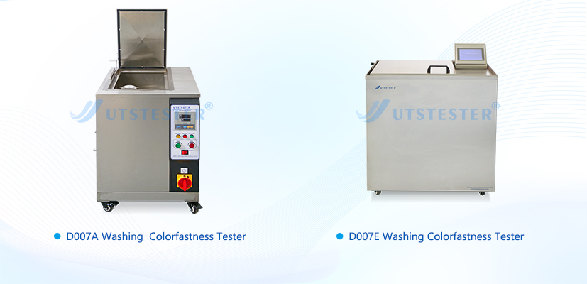
Colorfastness to washing: DIN EN ISO 105-C06, AATCC 61
Colorfastness to water: DIN EN ISO 105-E01, AATCC 107
Colorfastness to perspiration: DIN EN ISO 105-E04, AATCC 15
Resistance to artificial saliva and sweat: DIN 53160-1/-2
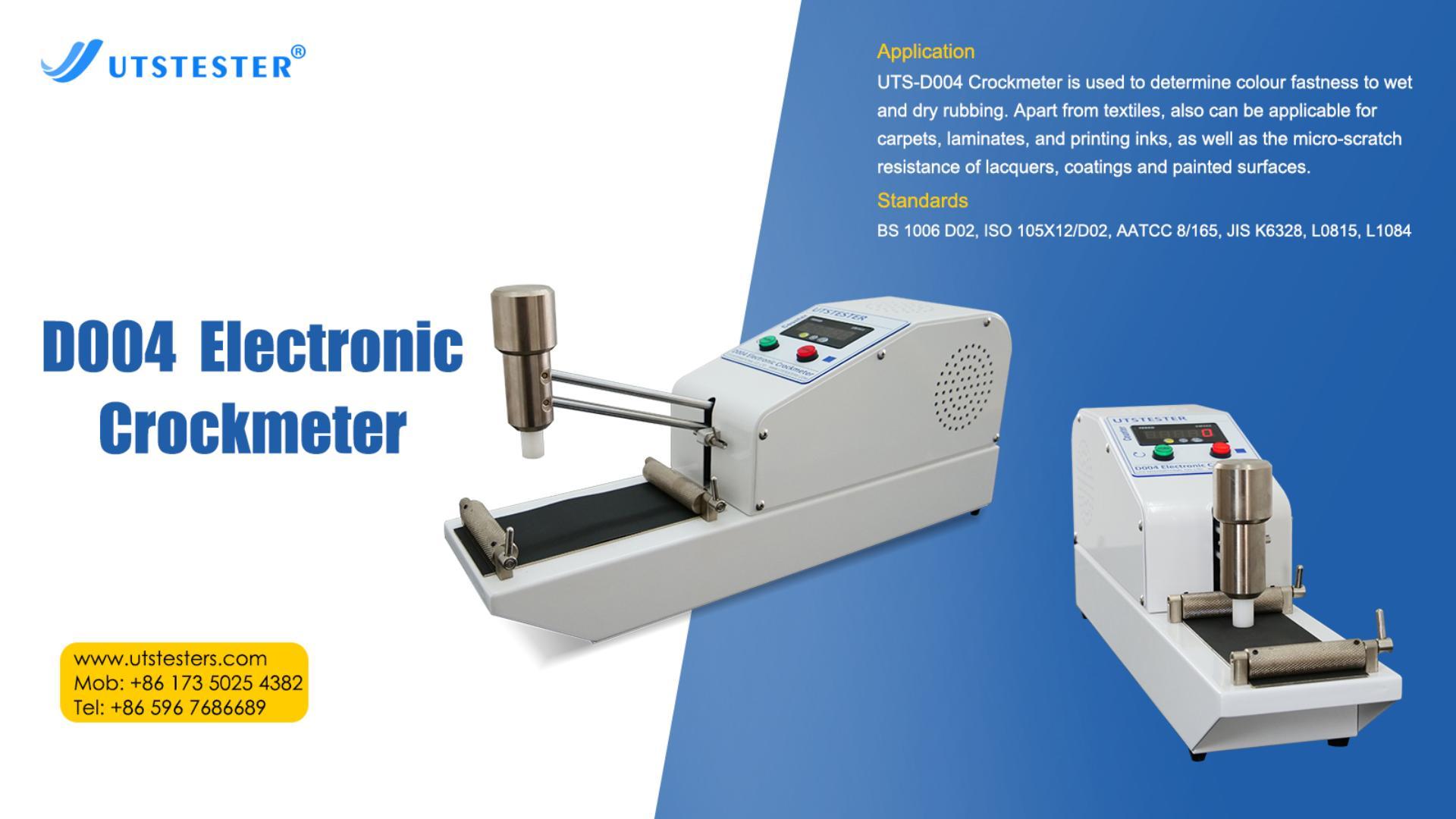
Resistance to friction: DIN EN ISO 105-X12, AATCC 8
Resistance to sublimation: DIN EN ISO 105-P01, AATCC 117
Lightfastness (sunlight): DIN EN ISO 105-B02, AATCC 16
Chlorine (pool) water fastness: DIN EN ISO 105-E03, AATCC 162
Saltwater fastness: DIN EN ISO 105-E02, AATCC 106
Dry cleaning colorfastness: DIN EN ISO 105-D01, AATCC 132
Heat pressing colorfastness: DIN EN ISO 105-X11, AATCC 133
Organic solvent colorfastness: DIN EN ISO 105-X05
Chlorine bleaching colorfastness: DIN EN ISO 105-N01, AATCC 188
Resistance to peroxide bleaching: DIN EN ISO 105-N02, AATCC 172
Resistance to water stains: DIN EN ISO 105-E07, AATCC 104
Resistance to alkali spots: DIN EN ISO 105-E06, AATCC 6
What is the significance of textile colorfastness testing?
The quality of colorfastness directly impacts human health and safety. If, during wear and use, dyes in textiles break down and fade due to the action of enzymes in sweat or saliva, this not only contaminates other garments or items but also allows dye molecules and heavy metal ions to be absorbed by the skin, thereby posing a risk to human health. Therefore, textile colorfastness testing is of great significance in evaluating the quality, usability, and health impact of textiles.
UTSTESTER — Textile Testing, Certification, and Research
UTSTESTER was established in 2005 as an exporter of laboratory testing instruments. All testing instruments comply with international testing standards, including ISO, AATCC, EN, DIN, JIS, ASTM, SATRA, GB, QB, BS, etc. The company has successfully obtained calibration certificates such as ISO 17025 and CE. To ensure continuous quality, UTS operations have been certified to the ISO 9001 standard.
Email: hello@utstesters.com
Direct: + 86 152 6060 5085
Tel: +86-596-7686689
Web: www.utstesters.com