Consumables for cryogenic rubber trimming machine – supply of liquid nitrogen
The frozen rubber deflashing machine, as an essential auxiliary manufacturing machinery in the production process of rubber enterprises, has been indispensable.
However, since its entry into the China mainland market around the year 2000, local rubber enterprises have little knowledge of the working principles and processes of the cryogenic deflashing machines.
Therefore, this article will provide a detailed introduction to the storage and supply methods of the cryogen, liquid nitrogen, for the cryogenic deflashing machines.
In the past, liquid nitrogen was typically stored in separate liquid nitrogen tanks. Therefore, when purchasing a cryogenic deflashing machine, it was necessary to buy a matching liquid nitrogen tank to ensure the proper operation of the machine.
The installation of the liquid nitrogen tank required approval from the relevant authorities, which was a cumbersome process, and the tanks themselves were expensive. This has led many factories that urgently need to use cryogenic deflashing machiness to improve work efficiency to hesitate, as it also involves a certain upfront cost investment.
Nanjing PEGE has introduced a liquid nitrogen manifold supply station to substitute for liquid nitrogen tanks.
This cryogenic deflashing system centralizes the gas supply of individual gas points, enabling multiple low-temperature Dewar flasks to be combined for centralized gas supply. It solves the cumbersome process of handling liquid nitrogen tanks, allowing customers to operate the cryogenic deflashing machines immediately after purchase. Above are good options for the container of the Liquid Nitrogen.
The main body of the cryogenic deflashing system simultaneously connects three bottles of liquid nitrogen Dewar flasks, and it also includes a port that can be expanded to accommodate four bottles.
The cryogenic deflashing system pressure is adjustable and equipped with a safety valve. It’s easy to assemble and can be mounted on the wall using a triangular bracket or placed on the ground using the bracket.
Nanjing PEGE always provide strong technical support for customer to better use the cryogenic deflashing system.
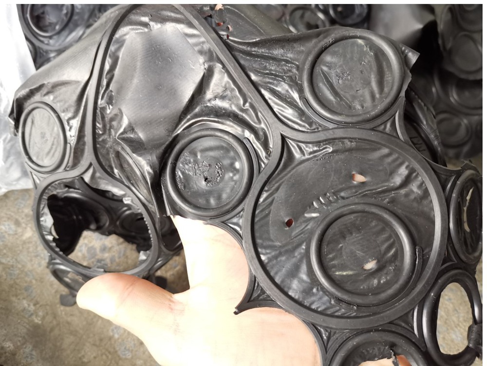
On the year of 2022, one customer from Colombia sent some samples for testing. The rubber parts to be deflashed are rubber O rings.
You can see from following photo:
There are many flashes which are difficult for manual deflashing.
After Cryogenic deflashing, we can get good results without flashes.
Even though the deflashing result was acceptable, customer was hesitating to make decision to purchase the cryogenic deburring machine due to the budget problem.
They paused the purchase this nitrogen shot blasting deflashing machine.
On the year of 2025, last year, customer restarted the project and we talked about the model and the offer and finally we made a deal to sell the cryogenic deflashing equipment Model PG-60T to customer.
It is a wonderful machine for automatic rubber deflashing process, it is well designed and well manufacturered.
No matter what industry you are working on, you have many choices when it comes to searching a point of sale (POS) system that suitable your demands. However components can be mixed and matched, your best solution is integrating them into one machine, thus all-in-one POS system was born.
Gilong’s new touch all in one POS system, integrated POS with printer and QR code scanner, to save the space for retailer furthest and makes operation more convenient and efficiency. That’s why more and more retailers give up using the traditional cash register and start to use all in one POS.
A main advantage of an all-in-one POS system is that it can provide us with more convenience. Not only it is easier to assemble and maintain due to the integrated technology and matured customer support, utilizing a system with individual components from the same supplier simplifies employee training.
Makes the cost less
Saving money has always been a cardinal question for business owners. By consolidating your POS system, you can run your business more efficiently, saving you money:
1.Maintenance will be easier and cheaper if all components come from the same supplier
2.Durable hardware tends to last longer than other types
3.Simplified device and user friendly features make employee’s training easier
Makes POS safer
A report indicated that 47 percent of business owners tend to upgrade their POS technology to meet the October 2015 EMV liability shift (1). By investing in EMV technology integrated into a single system, merchants are better protected from fraud liability. Many providers are offering all-in-one POS systems that employ new EMV technology for heightened security.
Simplifying payments with an szgilong all-in-one POS system has many benefits. Providing your business increased advantages – less trouble, increased space, security, and cost-effective –The all-in-one POS is a system that deserves to be considered.
Whenever you get behind the wheel, other than getting to wherever you are going, your primary concern is getting there safely. And to make sure you get there without a hitch, you need to check that your vehicle is working as it should.
So, before you set off, have you checked your hose clamps today?
Chances are, you haven’t or you might not even know what they are.
WHAT ARE HOSE CLAMPS?
Hose clamps secure hoses over fittings. The clamp prevents fluid from leaking at the connection, which is crucial for the smooth operation of a motor vehicle, pipe or water hose. And while nut and bolt clamps are often used for the same job, a hose clamp does a much better job.How do we get a good quality hose clamp? In the hose clamp manufacturing plant, a large number of hose clamps are produced every day to meet the large market demand.There are two ways to produce a large number of hose clamps, the first is manual and the second is machine. So what's the difference between a human and a machine?
As we all know, manual assembly is all processes, step by step manual operation, more than a dozen steps of cumbersome process, each link requires labor, requires a lot of manpower, material resources, the corresponding cost will increase a lot, in addition, manual efficiency is slow, but also because of the efficiency of each person is different, affect the shipment speed of the entire factory.
Therefore, in the age of automation, the convenience brought by machines is self-evident.Compared with the traditional manual control mode, the machine has many advantages such as stability, simple operation and so on. The work content is only to add semi-finished materials to the warehouse every 4 hours. The production efficiency is about 1000 pieces/hour, and the working accuracy is much higher than that of manual production, which meets the production requirements of the new generation of throat hoop manufacturers. The production is controlled by a PLC microcomputer, which records all data, and is equipped with a human-machine interface, ensuring that most technical parameters can be set on the touch screen.
The xmsinuowei machine can be fully automated assembly, simplifying the process, improving efficiency, and saving a lot of costs.Choosing a good fully automated machine is equivalent to four human workers. This is why Sinuowei has been focusing on the research and development, design and manufacture of machines for more than ten years. Because it can really change the traditional manual can not solve the problem.
In the global industrial handling sector, an efficient, flexible, and widely adaptable tool is crucial. The ETA Series Lithium Battery Electric Pallet Truck (Mini King Kong) from ZoNuo is designed to meet the needs of customers worldwide, boasting numerous advantages that deserve attention.
Whether you’re working in a warehouse, workshop, or logistics center, the ZoNuo Electric Pallet Trucks delivers exceptional performance. With a load capacity ranging from 1.5 to 2.0 tons, it strikes the perfect balance: powerful enough to handle medium-sized loads, yet compact enough to maneuver effortlessly in tight spaces—be it crowded warehouse aisles or busy factory floors—significantly boosting handling efficiency.
Its power system is equally impressive, featuring a range of lithium-ion battery options: 24V20AH-60AH and 48V10AH-30AH. These versatile configurations cater to diverse operational needs: smaller capacity batteries suffice for short, high-frequency tasks, while larger ones provide steady, long-lasting power for extended operations, eliminating constant worries about running out of charge.
The detachable battery design adds a layer of unmatched convenience. When the battery runs low, there’s no need to wait for recharging—simply swap in a fully charged spare battery, and the truck is instantly ready to go. This minimizes downtime and ensures uninterrupted workflow.
Most notably, the ZoNuo ETA Series Mini King Kong supports universal voltage worldwide. For global customers, this is a game-changer: no more hassle with voltage mismatches or the need for additional transformers. It seamlessly integrates into work environments across countries and regions, lowering usage barriers significantly.
Choosing the ZoNuo ETA Series Electric Pallet Truckmeans choosing efficiency, flexibility, and convenience. It’s more than just a handling tool—it’s a reliable partner that empowers your operations to run smoothly, no matter where in the world your business takes you.
Maximizing production efficiency is a primary objective of manufacturers who utilize computer numeric control (CNC) machines. Efficiency helps a company be more competitive, profitable and responsive to customer demand. Through these comprehensive strategies, we aim to help the manufacturers catalyze import/export efforts.
We will focus on several prominent areas of savings, including but not limited to advanced CAM software capabilities that work to time- and motion-optimize toolpaths, reducing workflow and material flow, selecting the machines and fixturing to maximize that efficiency, high-performance tooling and management systems, cutting parameters, automation and training to maintain equipment and operator skills.
Even implementing some of these suggestions can result in significant decreases in cycle time, material waste and machine downtime — and drive increased productivity and savings. Continue reading for some of the best practices you can apply now to begin getting the most out of your CNC investment.
Can You Improve the Efficiency of CNC Machines?
Yes, CNC machining output can be significantly enhanced with a focused approach. With all those interacting components; tooling, fixtures, code, parameters, equipment etc, there are numerous opportunities for optimization and performance enhancement. Before initiating any changes (toolpath optimization, tool refreshment, automation, etc.) you need to identify your present limitations and bottlenecks.
Manufacturers running older legacy CNC machines can still maximize efficiencies by upwards of 20 percent through improved workflows, tools, probes, and out-of-the-box fixturing solutions. And today's more sophisticated machines and software provide further opportunity for cycle time reduction and tool longevity. The strategies outlined below can lead manufacturers to best in class benchmarks.
Importance of Efficiency
In today's highly competitive manufacturing environment, companies must continually improve productivity and cost structures to thrive. For shops using CNC machining as a core competency, maximizing the efficiency of those processes is mandatory.
Failing to optimize machine performance can sink profit margins and lose business to rivals with better capabilities and economics.
Some key reasons that excelling at CNC efficiency matters include:
● Competitiveness: Efficient CNC usage is imperative for manufacturers to offer competitive pricing and lead times to customers. Meeting demands rapidly and cost-effectively depends directly on optimized machining.
● Profit Margins: Boosting efficiency directly improves profitability by cutting cycle times and material waste. Machining identical components faster and consuming less raw material saves real dollars.
● Shop Capacity: Streamlining the CNC process enables shops to take on more work and grow business. A 20% cycle time reduction expands available machine capacity by the same amount.
● Responsiveness: Having CNC efficiency gains translates into the responsiveness and agility to take on rush jobs or rapidly adjust to customer changes. Quick changeover and throughput make shops more adaptable.
● Quality: Refining machining processes through speed optimization, precision fixturing, and tool management inherently improves end part quality by reducing errors and variability.
Top 7 Tips to Improve the Efficiency of CNC Machine
1. Optimizing Toolpaths for Efficiency
One of the most impactful steps toward faster, leaner CNC machining is optimizing the toolpaths generated in CAM software. These toolpaths govern everything from machining sequence, tool selection, and travel paths to cutting strategies, heights, and spindle speeds.
Modern CAM systems provide extensive options to dial in high-efficiency toolpaths tailored to the part, tools, and machine in use.
Utilizing an advanced CAM system allows shops to program optimized toolpaths that significantly cut machining time while extending tool life and improving surface finish. Let's look at key efficiency-enhancing capabilities in CAM software:
● Determines optimal machining sequence considering part geometry, features, tool requirements, and machine kinematics. The sequence selected directly affects total cycle time.
● Defines toolpaths with minimized non-cutting travel that reduces cycle times by eliminating unnecessary tool movements. Close attention to travel keeps the tool constantly engaged in material removal.
● Manages material removal volumes by optimizing step-downs, stepovers, and other cutting parameters that influence tool load. This preserves tool life while avoiding excessive light cuts that waste time.
Efficient Toolpath Generation:
Some key strategies that CAM software employs to generate highly efficient toolpaths include:
● High-Speed Machining: CAM programming for HSM techniques like trochoidal milling cuts cycle times through faster feed rates and reduced tool loads. This is applied across suitable feature types.
● Toolpath Smoothing: Smooth spline interpolated toolpaths maintain precision while allowing faster feeds than point-to-point moves. This reduces jagged movements.
● Tool Axis Control: For 3+ axis machines, controlling tool orientation expands access to reduce tool changes and setups. Indexing the axis configurations expands efficiency.
● Plunge Roughing: Specialized roughing patterns focused on plunging cuts maximize material removal with lighter radial loads to preserve tool life.
● Rest Machining: Leaving a thin layer of stock material to remove in the final pass enables using the most efficient tool only where needed.
● Gouge Protection: Automatic gouge checking ensures safe toolpaths to avoid machine crashes that cause extensive downtime and recovery.
2. Effective Workflow Planning
While advanced CAM software handles much of the toolpath details, shops should still analyze overall workflow for process improvements. Often, greater efficiency gains come from updating workflows and material flows compared to tweaking machine parameters.
Steps to evaluate and streamline the machining workflow include:
● Map current workflow from raw stock to finished parts to visualize bottlenecks like queue times, transport batches, inspection stops, or other delays.
● Identify constraints limiting output like fixture changeover, tool availability, or probing. Look for what slows production flow.
● Overlap processes like machining one batch while probing the previous batch to make operations parallel rather than sequential.
● Right-size batches through work-in-progress analysis to find optimal transfer batch size between operations. Too large or small is inefficient.
● Standardize setups and workflow so all operators consistently follow the established best practice process. This is enabled through the setup of photos, videos, and checklists.
3. Proper Machine Selection and Setup
A key prerequisite for high-efficiency machining is matching part production to the appropriate CNC machine model and configuring the setup precisely. Having advanced software driving a simple 3-axis mill or asking a basic machine to hit tolerances beyond capability will inevitably result in disappointment.
Let's examine machine selection and setup considerations:
● Horsepower & Torque: Match machine motor capabilities to anticipated material removal rates and tooling requirements with overhead to spare. Underpowered machining leads to extensive wear and long cycle times from reduced speeds and feeds.
● Precision: Part tolerance and finish needs should guide builders to machines delivering the required accuracy through features like ballscrew quality, servo performance, material rigidity, and thermal stability.
● Tool Capacity: Necessary tool types, sizes, and counts dictate physical tool magazine capacity and carousel designs. Too little capacity risks time-consuming tool changeovers and recovery.
● Automation: For optimal efficiency, machine tools should be specified to match adjacent automation like robots, gantry loaders, and conveyors based on parts weights, volumes, transfer speeds, etc.
Precision Workpiece Setup
To leverage machine tool investments fully, shops must configure workholding solutions that locate parts precisely with quick changeover ability. This enables accessing the full working envelope and avoids setup-induced errors that reduce efficiency.
Some recommended setup practices include:
● Indicating parts on precise locating points using reliable techniques like edge finders, wireless probes, and laser systems.
● Modular fixturing with quick change capability to swap parts in and out rapidly.
● On-machine inspection via wireless probes to validate setup accuracy and identify any positional errors early.
● Secure clamping through sufficient clamp pressure and locators to avoid workpiece movement under cutting forces.
4. Advanced Tooling Strategies
Tooling is the critical bridge between machine tools and raw materials that governs factors like removal rates, operating speeds, power demands, and finish quality. Optimizing tooling selection, usage, and management is integral to smart CNC operation.
Utilizing the latest tool geometries and coatings while managing tool life actively through carousel systems helps improve program performance.
Significant cutting efficiency gains come from employing the newest generation of advanced cutting tools that outperform previous designs. Characteristics of these upgraded tools include:
● Tool Geometries: New shapes like variable helix/variable pitch end mills or Silent tools enhance finishes, accuracy, speeds, feeds, and life.
● Coatings: Refined coatings like Amorphous Diamonds further push heat and wear resistance to cut faster.
● Specialty Tools: Tools tailored for efficiency like harpoon drills, chatter-preventing geometries, or multichannel chip breakers improve specific operations.
These upgraded tools boost output through better speeds, feeds, and tool life. However, their higher performance capabilities can only be realized by optimizing cutting parameters.
Tool Management Systems
Besides using top-tier tooling, having an effective tool management system is mandatory for serious efficiency. Key functions of these advanced systems include:
● Tool Presetting: Measuring tools offline enables zeroing offsets to eliminate test cuts and manual intervention. This saves setup time and materials.
● Tool Life Tracking: By tracking tool usage and wear, operators know when tools need replacing before breakage or dimension errors occur.
● Tool Changers: Quick automatic tool changers minimize the downtime associated with swapping tools to keep machines cutting more of the time.
Through capabilities like presetting, tracking usage, and enabling fast changeovers, tool management solutions are indispensable for highly efficient CNC operation.
5. Optimizing Cutting Parameters
The cutting parameters specified in machining programs exert tremendous influence on cycle times, tool wear rates, machine loads, and other key efficiency factors.
While CAM systems suggest initial parameters, real-world variables mean optimal settings must be found through experimentation and monitoring.
The core parameters impacting efficiency include:
● Spindle Speeds: Rotational tool speeds dictate suitable feed rates. Optimal speeds balance tool life versus cycle time considerations.
● Feed Rates: The travel rate while engaged in the cut impacts forces, tool deflection, and heat generation. Finding the peak safe rate minimizes time.
● Depths of Cut: Determining maximum depths before tool overload lets operators program roughing cycles more aggressively to remove material rapidly.
Continually testing and adjusting these values is necessary to account for factors like actual tool sharpness, material variations, environmental changes, etc. Conservative CAM estimates must be pushed to reap efficiency gains.
6. Integrating Automation and Technology
Seeking to squeeze cycle time savings purely from CNC machines eventually hits diminishing returns. More impactful efficiency improvements come from integrating complementary automation and technology around the base machines.
This advanced equipment works to keep parts flowing with less human intervention, while software reduces programming bottlenecks.
Instead of relying on manual programming, automated CAM processes drive efficiency through:
● CAM Templates: Standardized program templates with stored best practices reduce programming time and enforce consistency.
● Parametric Programming: Rules-based programming adapts automatically to design changes without coding from scratch.
● Post Processor Tuning: Refining machine code output from CAM through optimal post configs avoids manual optimization of G-code. This ensures maximally efficient code generation tuned for the exact shop environment.
● Simulation: Automatic CAM simulation detects collisions, inefficiencies, and errors in toolpaths before attempting test cuts to save materials and unproductive machine time.
Together these automated CAM capabilities slash programming overhead while producing highly optimized machine code. This frees programmers to handle higher-value tasks.
7. Regular Maintenance and Training
While advanced tools, automation, and refined processes aim to minimize interruptions, breakdowns, and suboptimal performance are inevitable without diligent maintenance and training. Together these complementary initiatives maximize uptime and ensure operators follow best practices.
Even with resilient machine construction, continual operation subjects components to substantial wear. Without vigilant preventative maintenance, breakdowns cause extended outages. Critical activities include:
● Fluid Changes: Regularly replacing hydraulic oil, coolant, and lubricants based on usage intervals keeps damaging particles from circulating.
● Component Lubrication: Greasing ballscrews, way covers, and gearboxes avoids binding and sticking.
● Way Scraping: Precision hand scraping of mating surfaces maintains position accuracy as machines age.
Conclusion
This guide covers techniques like optimizing toolpaths, streamlining workflow, integrating automation, and more for dramatically increasing CNC machining efficiency.
While upgrading older equipment can deliver gains, modern CAM software and machinery combined with a focus on total process efficiency makes possible reductions in machining times of 50% or more versus legacy systems.
The common theme across these tips is analyzing each component and interaction for bottlenecks using data. Addressing limiting factors with tailored solutions leads to compounding gains.
Matching advanced tools and programming with smart workflows, maintenance, and operator skills builds a high-efficiency foundation for competitive manufacturing success.
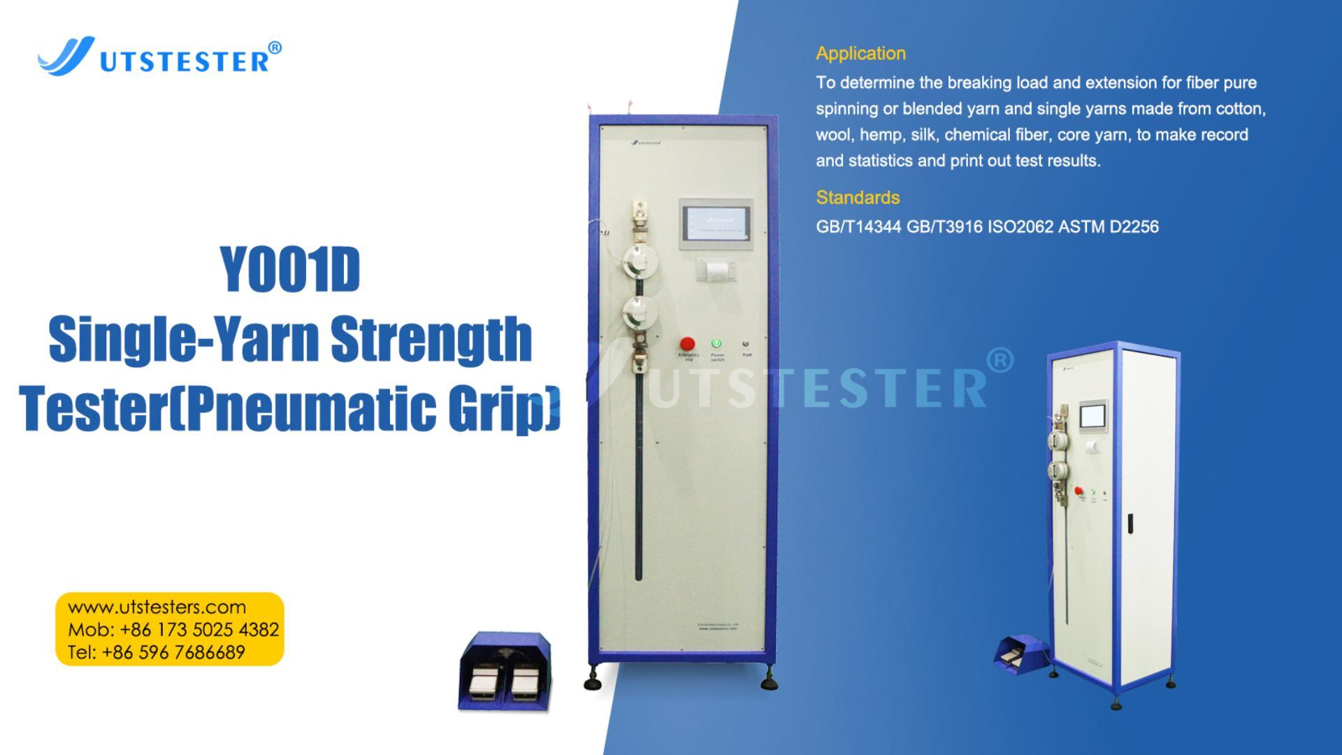
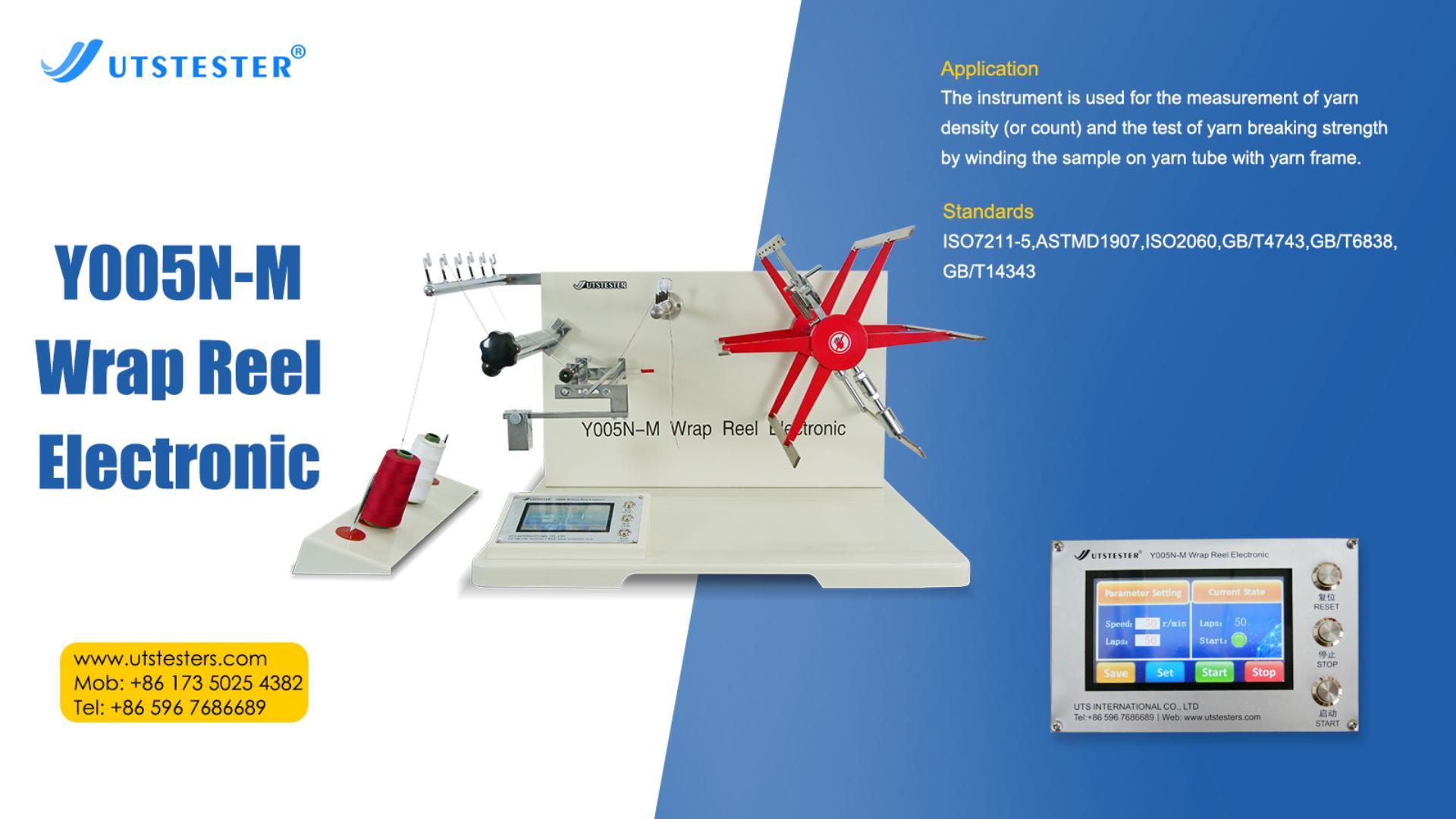
Single yarn strength tester is an important testing equipment in the textile industry, mainly used to measure the mechanical properties of a single yarn. This precision instrument plays a key role in textile production quality control, product development and material research. The following are the main uses of single yarn strength tester:
1. Yarn strength test
(1) Determine the breaking strength (maximum tensile force) of the yarn.
(2) Measure the elongation at break of the yarn.
(3) Evaluate the breaking work (energy required to break) of the yarn.
2. Quality control
(1) Monitor the quality stability during the yarn production process.
(2) Detect the performance consistency of different batches of yarn.
(3) Provide objective data basis for product classification.
3. Process optimization
(1) Evaluate the impact of different spinning processes on yarn strength.
(2) Compare the impact of different raw material ratios on the performance of the final product.
(3) Optimize spinning parameters to improve yarn strength.
4. R&D application
(1) Performance evaluation of new fiber materials.
(2) R&D testing of special yarns (such as high-strength and high-modulus yarns).
Durability testing of functional yarns.
5. Standard Compliance Testing
(1) Conduct standardized testing in accordance with international standards (such as ISO, ASTM).
(2) Provide mechanical property data required for product certification.
(3) Meet special testing requirements specified by customers.
The test results of single yarn strength testers are of great significance for predicting the performance of yarn in subsequent processes (such as weaving and knitting) and the durability of the final textile products. Modern single yarn strength testers are usually equipped with computer control systems that can automatically record test data and generate detailed analysis reports, greatly improving test efficiency and result reliability.
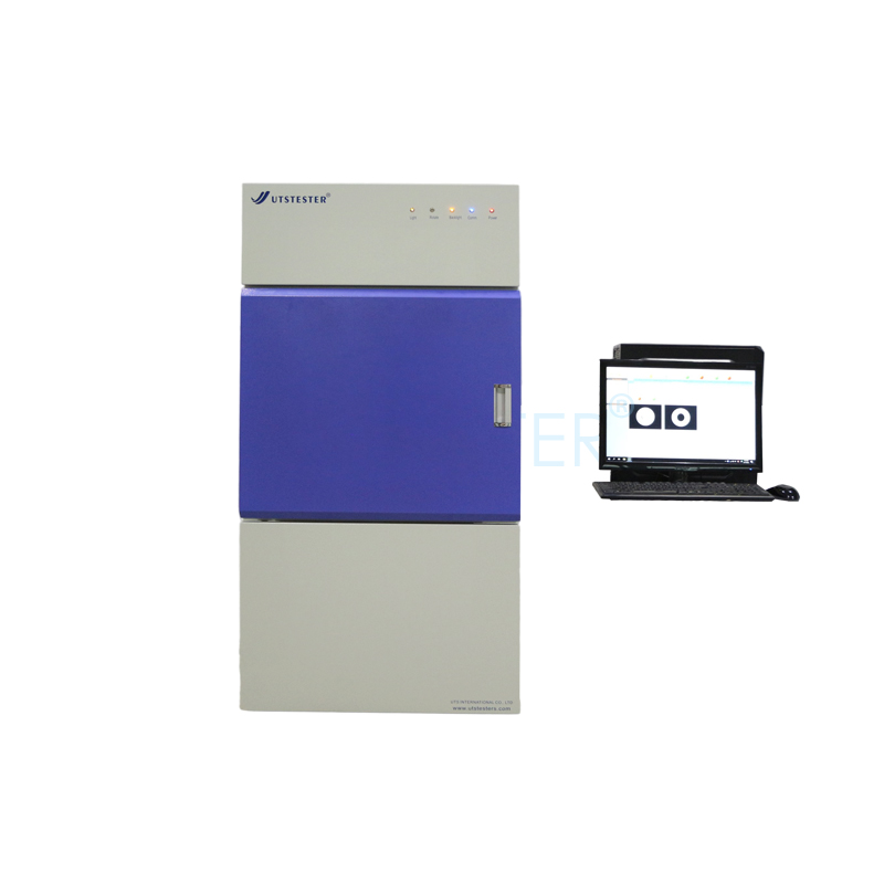
The automatic fabric vertical tester is a precision instrument used to measure the dimensional stability, tensile properties or drape characteristics of fabrics in a vertical state. Through the automatic control system, the equipment can accurately measure the deformation, elongation and other parameters of the fabric in a vertical hanging state, and is widely used in the fields of textile quality inspection, research and development, and production control.
II. Equipment composition
1. Main frame (including vertical guide rails).
2. Automatic clamping device (upper and lower clamps).
3. Force sensor system.
4. Displacement measuring device.
5. Control panel and display.
6. Data processing system.
7. Safety protection device.
III. Preparation before testing
1. Equipment inspection
(1) Confirm that the equipment is placed horizontally and the base is stable.
(2) Check that the power connection is normal (220V±10%, 50Hz).
(3) Confirm that all moving parts are well lubricated and there is no jamming.
(4) Check that the fixture is not damaged and the clamping surface is clean.
2. Sample preparation
(1) Cut the specimen according to the standard requirements (usually 300mm×50mm).
(2) The edges of the specimen should be flat and free of burrs.
(3) The number of specimens per group should be no less than 5.
(4) The specimen should be humidified under standard atmospheric conditions for at least 24 hours.
3. Parameter setting
Enter the test parameters through the control panel:
(1) Specimen length.
(2) Pre-tension (usually 5N).
(3) Test speed (standard is 100mm/min).
(4) Number of tests.
(5) Holding time (if necessary).
IV. Test operation steps
1. Power on and preheat:
Turn on the power, start the equipment, and preheat for 15 minutes
2. Fixture adjustment:
(1) Press the "fixture reset" button to return the upper and lower fixtures to the initial position.
(2) Adjust the fixture spacing to the standard distance (usually 200mm).
3. Install the sample:
(1) Place one end of the sample vertically into the upper fixture to ensure that there is no skew.
(2) Press the "upper clamp" button to fix the upper end of the sample.
(3) After applying pre-tension to the lower end of the sample, press the "lower clamp" button to fix it.
4. Start the test:
(1) Confirm that the safety protection device is closed.
(2) Press the "start test" button and the equipment will run automatically.
(3) Observe the sample status to ensure that there is no abnormality during the test process.
5. End of test:
(1) The equipment automatically stops and returns to the initial position.
(2) Record test data or print test report.
(3) Remove the tested sample.
6. Repeat test:
Replace new sample and repeat the above steps to complete the specified number of tests.
V. Data processing
1. The equipment automatically calculates and displays:
(1) Average elongation (%).
(2) Maximum force (N).
(3) Deformation recovery rate (%).
(4) Coefficient of variation (CV%).
2. Data export:
(1) Export test data through USB interface.
(2) Connect to computer and use special software for data analysis.
VI. Precautions
1. Safe operation:
(1) It is strictly forbidden to open the protective door during the test.
(2) Keep a safe distance when the equipment is running.
(3) Press the emergency stop button immediately in an emergency.
2. Maintenance:
(1) Clean the fixture and workbench after daily testing.
(2) Check the sensor accuracy regularly (recommended once every 3 months).
(3) Fill the guide rail with special lubricating oil every month.
3. Other precautions:
(1) Avoid using in a strong electromagnetic interference environment.
(2) When testing different fabrics, it is necessary to adjust the appropriate clamping force.
Yarn length measurement is an important part of quality control in the textile industry, used to measure parameters such as the length, linear density and twist of yarns. The following is the standard usage method of the yarn length measuring instrument:
I. Preparatory Work
1. Instrument inspection
(1) Confirm that the length measuring instrument is placed horizontally and all its components are intact.
(2) Check whether the counter, tensioning device and yarn guiding device are working properly.
(3) Clean the surface of the instrument and the yarn guiding components.
2. Environmental conditions
(1) Standard test environment: Temperature 20±2℃, relative humidity 65±3%.
(2) Avoid direct sunlight and strong air currents.
3. Sample preparation
(1) Take about 1.5 meters of yarn from the yarn barrel as the guide yarn.
(2) Remove the yarn segments with damaged or contaminated surfaces.
Ii. Operating Steps
1. Install the yarn
(1) Draw the yarn out from the bobbin and pass it through the tensioning device.
(2) Ensure that the yarn passes through all yarn guides without any cross-entanglement.
(3) Fix the end of the yarn on the winding shaft.
2. Parameter Settings
(1) Set the appropriate tension according to the type of yarn (usually 0.5cN/tex for cotton yarn and 0.25cN/tex for wool yarn).
(2) Set the winding length (the standard is 100 meters, and for short segment tests, it can be 10 meters or 20 meters).
(3) Set the number of pre-turns (usually 3 to 5 turns).
3. Start measuring
(1) Start the instrument, and the yarn begins to be wound evenly.
(2) Observe the winding process to ensure that the yarns are neatly arranged without overlap.
(3) The instrument will automatically stop when the set length is reached.
4. Data recording
(1) Record the actual length displayed by the counter.
(2) If the linear density is measured by the weighing method, remove the yarn frame for weighing (accurate to 0.01g).
(3) Calculate the actual linear density: Tex= weight (g)×1000/ length (m).
Iii. Precautions
1. Safe operation
Do not touch the moving parts when the instrument is in operation.
(2) Press the emergency stop button immediately in an emergency.
2. Measurement accuracy control
At least three samples should be tested for each batch of yarn and the average value should be taken.
(2) The tension fluctuation should be controlled within ±0.1cN.
(3) The winding speed should not be too fast (30-60m/min is recommended).
3. Maintenance and care
Clean the instrument after daily use.
(2) Regularly check the accuracy of the tension device.
(3) It should be calibrated by professionals every six months.
Iv. Common Problem Handling
1. Yarn breakage
(1) Check if the tension is too high.
(2) Check if there are burrs on the yarn guide.
(3) Confirm whether the strength of the yarn itself meets the standard.
2. Inaccurate counting
(1) Check whether the sensor is clean.
(2) Confirm whether the preset length unit is correct.
(3) Check whether the circuit connection is good.
3. Uneven winding
(1) Adjust the stroke of the yarn guide.
(2) Check whether the tension of the yarn is stable.
(3) Confirm whether the winding shaft is deformed.
The correct use of the yarn length measuring instrument can obtain accurate yarn length data, providing a reliable basis for subsequent quality control and process adjustment. Data should be recorded and archived in a timely manner after each test to facilitate quality tracking and analysis.
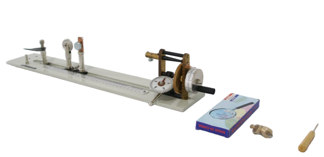
A yarn twist meter is an important instrument used in the textile industry to measure yarn twist (the number of twists per unit length). Its operating accuracy directly affects the evaluation of yarn quality. The following are detailed usage steps and precautions:
I. Instrument preparation
1. Equipment inspection
(1) Confirm that all parts of the twist meter (clamp, counter, rotating handle, etc.) are intact and can rotate flexibly.
(2) Check whether the dial or digital display is reset to zero to ensure that there is no residual data.
2. Calibrate the instrument
Use standard yarn or calibration rod for calibration, compare the measured value with the standard value, and the error must be within the allowable range (such as ±1%).
3. Environmental conditions
Operate in a standard temperature and humidity environment (such as 20±2℃, relative humidity 65±3%) to prevent the yarn from shrinking or stretching due to environmental changes.
II. Sample preparation
1. Sampling
(1) Randomly select at least 10 samples from the yarn batch, usually 25cm or 50cm in length (depending on the standard requirements).
(2) Avoid selecting yarn segments with joints or obvious defects.
2. Pre-humidification treatment
Balance the sample in the test environment for 24 hours to eliminate the effects of static electricity and humidity.
III. Test steps
1. Fix the yarn
(1) Fix one end of the yarn in the left clamp, and fix the other end in the right clamp after gently straightening it, ensuring that the yarn is not loose or overstretched.
(2) Adjust the clamping tension according to the yarn type (e.g. 0.5cN/tex is commonly used for cotton yarn).
2. Untwisting operation
(1) Manual mode: Slowly rotate the handle or knob to rotate the right clamp until the yarn twist is completely untwisted (fibers are parallel).
Automatic mode: After setting the parameters, start the instrument, automatically complete the untwisting and record the data.
3. Record the number of twists
(1) Observe the number of twists (T) displayed on the counter, or record it manually using the dial.
(2) Repeat the test 3 to 5 times and take the average value to improve accuracy.
4. Calculate twist
(1) Twist (twists/m) = number of twists (T) / sample length (m)
(2) For example: a 50cm sample is untwisted 30 times, then the twist = 30/0.5 = 60 twists/m.
IV. Precautions
1. Operating specifications
(1) The untwisting speed must be uniform (usually 10 to 30 turns/min). Too fast may cause yarn breakage or data distortion.
The clamp must be aligned to prevent the yarn from tilting or slipping.
2. Data Verification
If the difference between multiple test results of the same sample is greater than 5%, it is necessary to check the stability of the instrument or resample.
3. Maintenance
(1) Clean the clamp regularly to prevent fiber accumulation from affecting the accuracy.
(2) Add light lubricant to the rotating parts to maintain flexibility.
V. Application Standards
Test with reference to international standards (such as ISO 2061, ASTM D1422) or national standards (such as GB/T 2543.1) to ensure comparability of results.
Through standardized operation and regular calibration, the yarn twist meter can effectively evaluate the yarn strength and weaving performance, providing a reliable basis for quality control in textile production.