What Are the Different Types of Excavator Buckets and Their Uses?

What Are the Different Types of Excavator Buckets and Their Uses?

For construction contractors, equipment dealers, and project managers in Europe and North America, excavator buckets are not just basic attachments—they directly affect productivity, fuel efficiency, and operating costs. Using the wrong bucket can slow down progress, increase machine wear, and lead to unnecessary downtime.

Understanding the different types of excavator buckets and their real-world applications is essential for choosing the right solution for each job site. This guide explains the most common excavator bucket types and how they are used in actual working conditions.


1.Standard Excavator Buckets (General Purpose Buckets)

Standard excavator buckets are designed for everyday excavation tasks in soft to medium materials. They are commonly supplied as the original bucket with new excavators.

Typical applications include:

  • Soil and clay excavation
  • Sand and loose gravel handling
  • Residential and commercial construction projects

These buckets offer a balance between capacity, weight, and durability. For contractors working in relatively mild ground conditions, standard buckets are a cost-effective and versatile choice.


2.Heavy Duty Excavator Buckets

Heavy duty buckets are built for tougher environments where abrasion and impact are higher. Compared to standard buckets, they use thicker steel plates, reinforced cutting edges, and additional wear protection.

Common use cases:

  • Hard-packed soil
  • Mixed ground with stones
  • Road construction and foundation digging

In European and North American job sites where machines often operate long hours, heavy duty buckets help reduce maintenance frequency and extend service life, resulting in lower total ownership costs.


3.Rock Buckets

Rock buckets are specifically engineered for extremely harsh conditions. They feature high-strength, wear-resistant steel, reinforced ribs, and heavy-duty bucket teeth designed to penetrate rock and blasted materials.

Ideal for:

  • Quarry operations
  • Mining projects
  • Rocky terrain excavation

Using a standard bucket in these conditions can lead to rapid structural damage. Rock buckets are essential for maintaining efficiency and safety in demanding applications.


4.Trenching Buckets

Trenching buckets are narrow and designed to create precise, clean trenches with minimal material removal.

Common applications include:

  • Pipeline installation
  • Cable and utility projects
  • Drainage and irrigation systems

Their slim profile improves accuracy and reduces backfilling work, which is especially important for municipal and infrastructure projects across Europe and North America.


5.Tilting Excavator Buckets

Tilting buckets allow the operator to adjust the bucket angle hydraulically, increasing flexibility without repositioning the excavator.

Typical uses:

  • Slope finishing
  • Ditch cleaning
  • Landscaping and grading

These buckets are widely used in finishing work where precision and efficiency are critical.


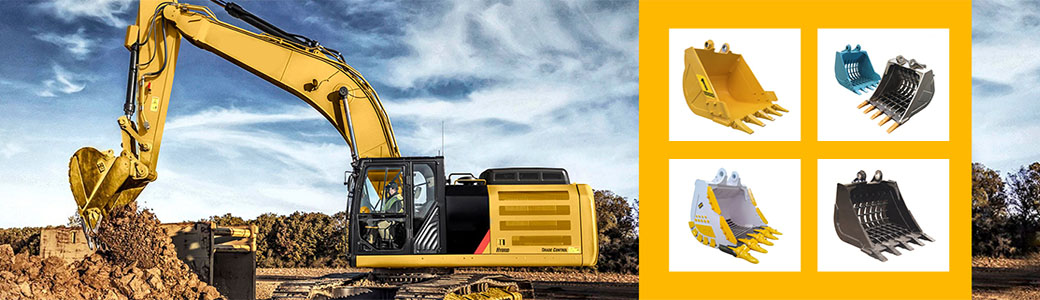
Customized Excavator Buckets for Real Job Conditions

Anhui Yuanpeng sales a full range of standard, heavy duty, and rock excavator buckets, as well as customized solutions based on real customer working conditions. By adjusting bucket structure, wear protection, and steel grade, Anhui Yuanpeng helps customers achieve longer service life and better performance in their specific applications. 

By working with experienced seller like Anhui Yuanpeng, buyers in Europe and North America can ensure their excavator buckets are built to match real job site demands—delivering durability, efficiency, and long-term value.


Looking for the right excavator bucket for your project?

Anhui Yuanpeng supplies standard, heavy duty, rock, and customized excavator buckets for construction, mining, and infrastructure projects worldwide.


Contact us to discuss your working conditions and get a professional bucket solution.


What Are the Hidden Costs of Using Low-Quality, Non-Certified Industrial Chains?

When sourcing industrial chains, the allure of a competitive price can be tempting. Procurement teams often focus on the initial purchase cost, overlooking the long-term, compounding expenses associated with low-quality, non-certified chains. This seemingly economical choice is, in fact, a false economy that can drastically inflate your Total Cost of Ownership (TCO) and disrupt operations.


Let's look at the impacts or potential costs that may arise.

1. The Crippling Cost of Unplanned Downtime

The most immediate and financially damaging hidden cost is the exponential increase in unplanned downtime. Low-quality chains, made from inferior metals or lacking the precise heat treatments required for critical components like pins and bushings, suffer from accelerated wear and rapid elongation.

While a premium, certified chain is engineered to deliver reliable service for tens of thousands of hours, a cheap, non-certified alternative might begin stretching or fail outright within months. When a chain snaps on a critical conveyor belt, assembly line, or power drive, the entire operation grinds to a halt. The cost of this stoppage far transcends the price of the failed component. It includes:

  • Lost Output: The forfeited revenue and margin for every minute the production line is idle, which can easily run into thousands of dollars per hour.
  • Emergency Labor: Overtime wages for maintenance crews scrambling to perform emergency repairs rather than planned, preventative work.
  • Scrap and Quality Issues: Material that was mid-process when the line stopped must often be discarded, further adding to waste and costs.


2. Excessive Maintenance and Accelerated Wear on Adjacent Components

Beyond catastrophic failures, poor chain quality silently drains maintenance budgets through friction and inefficiency. Inferior chains often possess poor dimensional consistency—meaning the pitch (distance between links) is irregular, and the roller/bushing concentricity is imprecise.

This lack of precision leads to rougher, non-uniform engagement with sprockets. The result is dramatically increased operating friction, which causes two significant hidden expenses:

  • Higher Energy Consumption: Increased friction means the motor must work harder, leading to higher amperage draw and a hidden spike in monthly energy bills.
  • Component Cascade Failure: The vibration, shock loads, and uneven tension caused by a low-quality chain accelerate the wear on the entire drive system, shortening the lifespan of expensive associated components, including sprockets, bearings, and even gearboxes.


3. Reduced Operational Throughput

High-performance industrial chains are designed not just to transmit power, but to do so with efficiency and durability under dynamic loading. Applications involving heavy shock loads, aggressive starting/stopping, or continuous high speeds demand uncompromising material integrity.

A manufacturer of quality chains ensures that components possess the necessary fatigue life and high strength to withstand these demanding cycles without compromise. Low-quality chains, however, often rely on minimal material or subpar alloys, leading to rapid material fatigue that limits the maximum load or speed at which the drive can safely operate. This forces managers to de-rate the machinery, effectively reducing the line's maximum potential throughput and hamstringing the plant’s overall capacity—a costly, long-term operational inefficiency.


4. Safety, Compliance, and Liability Risks

The most severe, though least frequent, hidden costs are those associated with safety and regulatory compliance. Non-certified chains rarely guarantee adherence to international standards like ISO or ANSI.

A catastrophic chain failure under full load is not just an equipment problem; it’s a severe workplace safety hazard that can cause injuries to personnel working nearby. Such incidents can trigger expensive investigations, regulatory fines, insurance premium hikes, and potential liability claims—costs that dwarf any initial material savings. Furthermore, in specialized industries like food processing, using non-certified stainless steel chains can lead to issues with hygiene, corrosion, and contamination, resulting in compliance failures and expensive product recalls.


The initial saving achieved by choosing a cheap chain is a classic example of "penny wise, pound foolish." The true Total Cost of Ownership—driven by production downtime, frequent maintenance, component replacements, energy waste, and safety risks—will inevitably wipe out the initial savings many times over.

To ensure long-term reliability, maximum uptime, and proven quality that meets stringent international standards, it is essential to partner with reputable suppliers known for their engineering excellence. Companies that focus on precision manufacturing and rigorous testing, such as Anhui Yuanpeng, help industrial operators understand that buying quality is not an expenditure, but a necessary investment in operational resilience and long-term profitability.

Advantages of Using Oil Temperature Controllers for Mold Heating

In industrial molding processes—from plastic injection to composite curing—mold temperature directly dictates product quality, production efficiency, and operational costs. While water-based and electric heating systems have their uses, oil temperature controllers (oil TCUs) stand out for high-heat precision and long-term reliability. Let’s explore why these systems have become indispensable for demanding manufacturing environments.
1. Unmatched High-Temperature Capability
Unlike water (limited to ~100°C at atmospheric pressure), thermal oil boasts exceptional thermal stability and a high boiling point, enabling oil TCUs to operate at 200–350°C (and up to 400°C with specialized models) . This makes them ideal for heat-intensive processes like:​
  • Rubber vulcanization requiring 180–250°C​
  • Carbon fiber composite curing at 280–320°C​
  • Hot pressing of high-performance resins​
For example, a Zhejiang New Energy Enterprise producing battery tray laminates relied on a 350°C oil TCU to achieve consistent resin curing, boosting product flatness compliance rate to 98% .
2. Precision & Uniformity: The Quality Drivers
Oil TCUs deliver ±1°C temperature accuracy (and up to ±0.1°C with advanced PID control) by circulating heated oil evenly through mold cavities . This eliminates hotspots that cause defects like warping, surface blemishes, or uneven curing.​
In a Jiangsu chemical enterprise’s resin production, an oil TCU with PID regulation maintained reaction temperatures between 80–200°C with minimal nudulation,cutting batch defects to zero and shortening setting time by 20% . For large molds (e.g., automotive panels), oil’s superior heat retention ensures uniform heating across all sections—something electric heating often struggles with .
3. Energy Efficiency & Low Lifecycle Costs
While electric heating may offer faster startup, oil TCUs excel in sustained energy efficiency. Their closed-loop design minimizes heat loss, and thermal oil’s long lifespan (5–8 years with proper maintenance) reduces replacement costs .​
Comparative data shows oil systems cut energy consumption by 15–20% versus electric alternatives . A Shandong Rubber Factory swapped to a dual-loop oil TCU and saw total operational costs drop by 30%, thanks to lower energy use and fewer repairs .
4. Versatility Across Industries
Oil TCUs adapt to diverse molding needs, from small-batch precision parts to high-volume production lines. Key applications include:​
  • Plastics: Injection molding of engineering plastics (e.g., PEEK) requiring stable 250°C+ temperatures​
  • Chemicals: Reaction temperature control for heat-sensitive compounds​
  • Composites: SMC/BMC molding and out-of-autoclave curing​
Manufacturers can customize systems with features like segmented temperature control,rapid cooling (via plate heat exchangers), or remote monitoring via PLC integration .
5. Robust Safety & Reliability
Oil TCUs incorporate multi-layer protection to mitigate industrial risks:​
  • Leak detection: Sensors trigger alarms for oil seepage​
  • Overload safeguards: Automatic shutdown for temperature/pressure anomalies​
  • Explosion-proof designs: Suitable for volatile environments (e.g., chemical plants)​
These features reduce downtime and compliance costs—critical for industries like pharmaceuticals and aerospace where safety is non-negotiable .
 
Final Thoughts
Oil temperature controllers are more than just heating devices—they’re quality assurance tools. By combining high-temperature capability, precision, and efficiency, they help manufacturers reduce defects, cut costs, and scale production. Whether you’re molding automotive components or advanced composites, an oil TCU is a long-term investment in operational excellence.
Ready to optimize your mold heating? Consult with a supplier to tailor an oil TCU to your temperature range, mold size, and production goals.

Comparison Water vs Oil Temperature Controllers - Which Is Better?

When it comes to industrial temperature control, choosing between water-based and oil-based controllers can make or break your production efficiency, product quality, and long-term costs. These two systems operate on the same core principle—circulating a heat transfer medium to regulate equipment temperature—but their unique properties lead to stark differences in performance. Let’s dive into a detailed comparison to help you answer the critical question: Which is better for your needs?​
 
1. Core Performance: Temperature Range & Precision​
The most fundamental distinction lies in their temperature capabilities, dictated by the physical properties of their media.​
Water Temperature Controllers​
 
Water’s boiling point (100°C at atmospheric pressure) limits its natural range, but pressurized systems can extend this to 180°C . This makes them ideal for low-to-moderate temperature requirements. Water’s high specific heat (1.0 cal/g°C) enables rapid heat absorption and transfer, meaning it reaches setpoints quickly—critical for processes needing fast thermal response.​
Modern water controllers offer impressive precision, often within ±0.1°C to ±1°C , thanks to advanced PID controllers and stainless steel circulation systems. For example, Xiecheng Machinery’s water-based models feature LCD displays and Siemens components to maintain this accuracy .​
 
Oil Temperature Controllers​
Oil-based systems thrive in high-heat environments. Using thermal oils (mineral or synthetic), they routinely reach 200°C to 350°C, with specialized units hitting 360°C or even 500°F (260°C) . Unlike water, oil doesn’t boil at these temperatures, eliminating vapor pressure risks in open-loop setups.​
While oil’s specific heat is lower (0.361 cal/g°C) , leading to slower heating than water, its thermal stability ensures consistent temperatures over long runs. Precision matches water-based systems at ±0.1°C to ±1°C , with units like Tool-Temp’s Matic Oil 360 using predictive iris control to avoid fluctuations .​
Verdict: Oil wins for high-temperature needs; water excels in rapid response for moderate ranges.​
 
2. Application Suitability: Which Fits Your Industry?​
Your production process is the ultimate decider—here’s how each system maps to common industries.​
 
Water Controllers Shine In:​
  • Plastic Injection Molding: Ideal for molds requiring 40°C–100°C, where quick cooling prevents part warping .​
  • Food & Beverage: Water’s cleanliness and low contamination risk make it perfect for dough mixing, chocolate extrusion, and wine fermentation .​
  • Lab Research: Economical and easy to purify, water-based systems suit experiments with temperature limits under 180°C .​
  • Small-Scale Manufacturing: Compatible with most compact equipment, offering cost-effective thermal control .​
Oil Controllers Dominate In:​
  • Metal Processing: Die casting and heat treatment demand 200°C+ temperatures, where oil’s stability prevents thermal shock .​
  • Chemical/Pharmaceutical Production: Jacketed reactors and high-viscosity mixing rely on oil’s 300°C+ capability to avoid batch failures .​
  • Printing & Lamination: High-temperature oil systems ensure uniform drying of inks and adhesives .​
  • Automotive Testing: Engine test stands use oil controllers to simulate extreme operating temperatures up to 260°C .​
Verdict: Match the medium to your temperature threshold—water for °C, oil for >200°C.​
 
3. Cost & Maintenance: Short-Term Savings vs. Long-Term Investment​
Budget considerations extend beyond upfront costs to ongoing upkeep.​
Water Controllers: Low-Cost, Low-Effort​
  • Initial Investment: 30–50% lower than oil systems , with basic models starting under $5,000 .​
  • Operating Costs: Water is free and abundant, cutting fluid replacement expenses to near-zero .​
  • Maintenance: Simple routine tasks—cleaning SUS304 stainless steel filters to prevent scale buildup and occasional sensor calibration . No specialized skills required for repairs .​
Oil Controllers: Higher Costs, Higher Commitment​
  • Initial Investment: Premium components (high-temp pumps, expansion tanks) push costs to ​
    16,000 , with custom systems costing more.​
  • Operating Costs: Thermal oil replacement (every 6–12 months) adds recurring expenses, and energy use is slightly higher due to lower conductivity .​
  • Maintenance: Requires regular oil quality checks, seal inspections (to prevent leaks), and heater calibration . Specialized thermal oils (e.g., HTF HF-2) must be used to avoid system damage.​
Verdict: Water saves money upfront and long-term for basic needs; oil justifies costs for high-heat critical processes.​
 
4. Safety & Environmental Impact​
Both systems have risks, but mitigation strategies vary widely.​
Water Controllers: Mild Risks, Easy Mitigation​
  • Key Hazards: Pipe corrosion (from unfiltered water) and steam leaks (at high pressure) .​
  • Safety Features: Modern units include auto-shutdown for blockages and pressure relief valves .​
  • Eco-Footprint: Near-zero environmental impact—water can be recycled, and no toxic spills risk .​
Oil Controllers: Serious Risks, Strict Protocols​
  • Key Hazards: Oil leaks (from degraded seals) pose fire risks at high temperatures , and spilled thermal oil contaminates soil/water .​
  • Safety Features: Reliable systems use 400°C-resistant pumps , closed-loop designs , and leak detection sensors . Tool-Temp’s Matic Oil 360 adds inverter technology to reduce overheating risks .​
  • Eco-Footprint: Requires proper disposal of used oil; some synthetic oils are biodegradable but costly .​
Verdict: Water is safer and greener; oil demands rigorous safety protocols.
 
Conclusion: There’s No "Better"—Only "Better For You"​
Water and oil temperature controllers are not competitors but specialized tools. Water-based systems deliver affordable, fast, and safe control for moderate temperatures, making them the workhorse of general manufacturing. Oil-based units reign supreme in high-heat applications where stability and precision justify higher costs and stricter maintenance.​
Assess your process’s temperature demands, budget, and safety requirements first—then let the medium match the mission. Whether you’re extruding chocolate or die-casting metal, the right controller turns thermal management from a challenge into a competitive advantage.​


Have you encountered other problems with water temperature controllers? Share your experiences in the comments below!

How to Choose the Right Water Temperature Controller for Your Application

Whether you’re managing a industrial process, maintaining a commercial HVAC system, or optimizing a home aquarium, selecting the right water temperature controller is critical to ensuring efficiency, reliability, and performance. With a wide range of options available—from basic on/off switches to advanced programmable systems—navigating the choices can be overwhelming. This guide breaks down the key factors to consider, helping you find a controller that aligns perfectly with your specific application needs.​
1. Define Your Application Requirements
The first step in choosing a water temperature controller is to clearly outline your use case. Start by asking these fundamental questions:​
  • What is the temperature range you need to maintain? Industrial processes might require precise control between 0–200°C, while a home fish tank may only need 22–28°C. Ensure the controller’s operating range matches your needs—some models are designed for low-temperature applications (e.g., refrigeration) and others for high-heat environments (e.g., boiler systems).​
  • How precise does the temperature control need to be? Applications like laboratory equipment or pharmaceutical manufacturing demand tight accuracy (±0.1–0.5°C), while general HVAC systems may tolerate a wider variance (±1–2°C). Look for controllers with a “temperature resolution” specification to gauge precision.​
  • What is the flow rate and volume of water? High-flow industrial systems require controllers with robust sensors and fast response times to avoid lag, while small-volume applications (e.g., coffee machines) can use more compact, low-power models.​
  • Is the application indoor or outdoor? Outdoor controllers need weatherproofing (IP rating ≥65) to withstand moisture, dust, and temperature fluctuations, whereas indoor units may prioritize compactness or integration with existing systems.​
2. Understand Controller Types
Water temperature controllers come in three primary types, each suited to different scenarios:​
  • On/Off Controllers (Simple Thermostats): The most basic and affordable option. They activate a heater or cooler when the temperature falls below a setpoint and deactivate it when the setpoint is reached. Ideal for low-precision applications like residential hot water heaters or greenhouses. Limitation: May cause temperature swings (hysteresis) due to delayed response.​
  • Proportional (P) Controllers: Adjust the output (e.g., heater power) proportionally to the difference between the actual temperature and setpoint. For example, if the temperature is slightly below the setpoint, the heater runs at partial power; if it’s far below, it runs at full power. Reduces temperature swings compared to on/off models, making them suitable for commercial appliances (e.g., restaurant dishwashers) or small industrial processes.​
  • Proportional-Integral-Derivative (PID) Controllers: The most advanced and precise type. They combine proportional control with integral (corrects long-term errors) and derivative (predicts future changes) adjustments to maintain a stable setpoint. Ideal for high-precision applications like laboratory reactors, semiconductor manufacturing, or medical equipment. Note: PID controllers may require calibration (tuning) for optimal performance.​
3. Consider Key Features
Beyond basic functionality, look for features that enhance usability and compatibility with your system:​
  • Sensor Compatibility: Controllers rely on sensors (e.g., thermistors, RTDs, thermocouples) to measure temperature. Ensure the controller supports the sensor type best suited to your application: RTDs for high accuracy (laboratories), thermocouples for high temperatures (industrial furnaces), or thermistors for cost-effectiveness (home use).​
  • Output Options: The controller’s output must match your heating/cooling equipment. Common outputs include relay (for on/off devices like immersion heaters), analog (4–20mA or 0–10V for variable-speed pumps), or digital (Modbus for smart systems). For example, a PID controller with a 4–20mA output is ideal for controlling a variable-frequency drive (VFD) in a water circulation system.​
  • User Interface: Choose a controller with an intuitive interface—LCD displays for easy setpoint adjustment, touchscreens for complex programming, or remote access (via Wi-Fi/Bluetooth) for monitoring from a smartphone. Industrial users may prefer controllers with programmable logic controllers (PLCs) for integration with factory automation systems.​
  • Safety Features: Critical for applications involving high temperatures or pressure. Look for over-temperature protection (shuts down the heater if temperature exceeds a safe limit), low-water level detection (prevents dry heating), or alarm outputs (triggers alerts for system failures).​
  • Energy Efficiency: Opt for controllers with energy-saving features like adaptive control (adjusts output based on usage patterns) or scheduled programming (e.g., lowers temperature during off-hours for HVAC systems). This can reduce operational costs for commercial and industrial users.​
4. Evaluate Environmental and Installation Factors
  • Environmental Conditions: Ensure the controller can withstand the operating environment. For harsh industrial settings (e.g., factories with dust or chemicals), choose a rugged, NEMA-rated enclosure. For corrosive environments (e.g., marine applications), look for controllers with stainless steel components.​
  • Installation and Size: Compact controllers are ideal for space-constrained areas (e.g., under-sink water heaters), while rack-mountable models are better for industrial control panels. Consider wiring requirements—some controllers offer plug-and-play installation, while others may require professional wiring for complex systems.​
  • Cost vs. Value: Set a budget, but prioritize long-term value over upfront cost. A cheaper on/off controller may save money initially but could lead to higher energy bills or product defects in precision applications. Investing in a PID controller for a laboratory or manufacturing process can improve product quality and reduce downtime.​
5. Test Compatibility and Seek Expert Advice
Before making a final decision:​
  • Check System Compatibility: Ensure the controller’s voltage (120V, 240V, 480V) matches your power supply, and that the maximum current rating can handle your equipment (e.g., a heater drawing 10A requires a controller with a relay rated for at least 10A).​
  • Consult Manufacturers or Engineers: If your application is complex (e.g., multi-zone HVAC systems or industrial process control), reach out to the controller manufacturer for technical support. They can help you select a model with the right specifications or customize a solution for your needs.​
  • Read Reviews and Case Studies: Look for feedback from users with similar applications. For example, a restaurant owner might benefit from reviews of controllers used in commercial kitchens, while a researcher can reference case studies of PID controllers in laboratory settings.​
Conclusion
Choosing the right water temperature controller boils down to matching the controller’s capabilities to your application’s unique needs. Start by defining your temperature range, precision requirements, and system specifications, then select a controller type (on/off, P, PID) and features that align with those goals. Whether you’re looking for a simple thermostat for your home or a high-precision PID controller for industrial use, taking the time to evaluate these factors will ensure you invest in a reliable, efficient solution that meets your needs for years to come.
Have you used a water temperature controller in your facility? Share your experience or questions in the comments below!​


How to Maintain an Oil Temperature Controller for Long-Term Use

An oil temperature controller (TCU) is the backbone of precision temperature management in industries like plastic molding, chemical processing, and laboratory testing. Neglecting maintenance can lead to erratic temperature control, component failure, or even safety hazards. To keep your TCU running reliably for years, follow this comprehensive maintenance guide.
1. Daily Routine: The Foundation of Longevity
Consistent daily checks prevent small issues from escalating into costly breakdowns. Start by verifying the oil level through the sight glass—low levels cause sensor misreads and pump damage, while overfilling risks pressure buildup . Next, inspect for leaks: check pipeline connections, seals, and valve joints for oil stains, as even minor leaks degrade performance over time .​
Monitor operational parameters closely. A stable TCU should maintain temperature within ±1°C of the setpoint; fluctuations beyond this may signal sensor drift or oil degradation . Listen for unusual noises from the pump or heater—grinding sounds often indicate worn bearings, while humming could mean electrical issues . Finally, keep the exterior clean: wipe dust from vents and control panels with a dry cloth to ensure proper heat dissipation .
2. Thermal Oil Management: The Lifeblood of Your TCU
Thermal oil degradation is the leading cause of TCU failure, so proactive oil care is non-negotiable. First, always use manufacturer-approved oil—mixing different grades creates sludge that clogs lines and damages heaters .​
Know when to replace oil by combining three indicators:​
  • Appearance: Dark, cloudy oil or visible sediment means oxidation has occurred .​
  • Performance: If heating takes 20% longer than usual or temperature swings increase, oil efficiency has dropped .​
  • Schedule: For lab use (2–4 hours/day, ≤200°C), replace every 1.5–2 years; industrial high-heat use (8–12 hours/day, ≥250°C) requires changes every 6–12 months .​
When changing oil, drain the system completely and flush the tank with a manufacturer-recommended cleaner to remove residue . Never reuse old oil, even if it looks clean—hidden contaminants accelerate wear.
3. Core Component Care: Sensors, Actuators, and Electronics
Each TCU component has unique maintenance needs that directly impact accuracy and lifespan.​
Temperature Sensors​
Sensors like PT100 probes are critical for precise readings. Every quarter, calibrate them using a multimeter: at 0°C, resistance should be 100Ω ±0.1Ω . Regularly clean the probe with a soft brush to remove oil buildup, which distorts measurements . Ensure sensors are installed in oil flow-rich areas—avoid air pockets or dead zones that cause false readings . If your TCU shows "HHH/LLL" errors, check for loose wiring or sensor damage .​
Heaters and Cooling Systems​
Heaters fail when oil contaminants burn onto their surfaces. Inspect heating elements annually: look for carbon deposits and use a non-abrasive tool to clean them . Test for short circuits with a multimeter—replace elements if resistance is abnormal .​
For cooling systems, clean condenser fins monthly with compressed air (keep pressure below 0.3MPa) to prevent overheating . Replace dry filter every 4000 hours, as saturated filters reduce cooling efficiency by 60% .​
Electrical System​
Tighten wiring connections every three months to prevent overheating from poor contact . Check 继电器触点 for 碳化 —if resistance exceeds 0.5Ω after 2000 hours of use, replace the relay . Use an infrared thermal camera to scan terminals: a 15°C temperature difference between connections signals a problem .
4. Preventive Maintenance: Avoiding Catastrophic Failure
Preventive steps reduce downtime by addressing issues before they cause breakdowns.​
  • Filter Care: Clean inlet filters monthly (weekly in dusty environments) to prevent clogging, which strains the pump .​
  • Leak Testing: Use a pressure gauge to check for system leaks quarterly—drop-offs in pressure indicate seal damage .​
  • Vibration Monitoring: Install vibration sensors on pumps; readings above 4mm/s signal bearing wear .​
  • Environment Control: Keep the TCU in a dry, ventilated area with temperatures between -20°C and 70°C . Avoid direct sunlight, which accelerates plastic component aging .​
5. Troubleshooting Common Issues
Even with maintenance, problems arise. Here’s how to address frequent issues:​
  • Temperature Fluctuations: Check for bad earth(add a shielded cable if needed) or dirty filters .​
  • Heater Not Working: Verify the relay has 12VDC output and inspect for wiring errors .​
  • Oil Leaks: Replace worn O-rings and gaskets—use only manufacturer-approved parts .​
Final Tips for Long-Term Reliability​
  • Keep a maintenance log tracking oil changes, calibrations, and repairs—this identifies wear patterns .​
  • Upgrade aging systems with redundancy: add a backup mechanical thermostat set 5°C above the main controller .​
  • Train operators to avoid frequent start-stop,which stresses components .​
By integrating these practices into your routine, you’ll extend your TCU’s lifespan by 50% or more while maintaining the precision your processes demand. Remember: a well-maintained controller isn’t just an asset—it’s a guarantee of consistent production quality.
Have you encountered other problems with water temperature controllers? Share your experiences in the comments below!


Troubleshooting Common Problems in Water Temperature Controllers A Comprehensive Guide

Water temperature controllers are the unsung heroes of countless industries—from HVAC systems and aquaculture to food processing and residential hot water heaters. These devices ensure precise temperature regulation, which is critical for efficiency, safety, and product quality. However, like any mechanical or electronic equipment, they’re prone to malfunctions that can disrupt operations, waste energy, or even cause damage. In this blog, we’ll break down the most common issues with water temperature controllers, their root causes, and step-by-step solutions to get your system back on track.​
1. Temperature Readings Are Inaccurate
One of the most frustrating problems is when the controller’s display doesn’t match the actual water temperature. This can lead to overheating, underheating, or inconsistent performance.​
Common Causes:​
  • Faulty Temperature Sensor (Thermistor/RTD): The sensor is the "eyes" of the controller—if it’s damaged, dirty, or incorrectly calibrated, readings will be off. Sensor probes can corrode over time (especially in harsh water conditions), develop loose connections, or suffer from internal wiring damage.​
  • Calibration Drift: Over time, controllers lose calibration due to wear and tear, voltage fluctuations, or environmental changes (e.g., extreme temperatures in the control panel).​
  • Sensor Placement: If the probe is placed in a dead zone (e.g., too close to a heater, pump, or pipe wall), it won’t measure the average water temperature accurately.​
Troubleshooting Steps:​
  1. Verify with a Reference Thermometer: Submerge a reliable digital thermometer in the same water source to confirm the actual temperature. If there’s a significant discrepancy, the controller or sensor is at fault.​
  1. Inspect the Sensor: Remove the probe and check for corrosion, scaling, or physical damage. Clean it with a soft brush or vinegar solution (for mineral buildup) and ensure wiring connections are tight and free of rust.​
  1. Recalibrate the Controller: Refer to the manufacturer’s manual to recalibrate the device. Most controllers have a calibration mode where you can adjust the display to match the reference thermometer’s reading.​
  1. Adjust Sensor Placement: Relocate the probe to a central area of the water system, away from heat sources, pumps, or stagnant water. Ensure it’s fully submerged (for liquid sensors) and secured to prevent movement.​
2. Controller Fails to Turn On/Respond
If the controller doesn’t power up, display anything, or react to button presses, the issue is likely electrical or mechanical.​
Common Causes:​
  • Power Supply Issues: Tripped circuit breakers, blown fuses, loose power cords, or faulty electrical outlets can cut power to the controller.​
  • Internal Component Failure: Burned-out transformers, capacitors, or circuit boards (due to voltage spikes, moisture, or age) can render the controller non-functional.​
  • Mechanical Jam: Stuck buttons or a damaged front panel (from impact or wear) may prevent the controller from responding.​
Troubleshooting Steps:​
  1. Check Power Connections: Ensure the power cord is firmly plugged into a working outlet. Test the outlet with another device (e.g., a lamp) to confirm it’s supplying power. Reset tripped breakers or replace blown fuses in the electrical panel.​
  1. Inspect for Moisture/Damage: If the controller is installed in a damp environment (e.g., a basement or utility room), check for water intrusion. Moisture can short-circuit internal components—dry the device thoroughly (if safe) or replace it if damage is visible.​
  1. Test with a Multimeter: For advanced users, use a multimeter to check for voltage at the controller’s power input. If there’s no voltage, the problem is in the power supply; if there is voltage but the controller doesn’t respond, internal components may be faulty.​
  1. Reset the Controller: Many models have a reset button (often hidden behind a small hole) or a factory reset option in the menu. Perform a reset to clear any glitches—note that this will erase custom settings.​
  1. Replace Faulty Parts: If internal components (e.g., transformers) are visibly burned or damaged, contact the manufacturer for replacement parts or consider a full controller replacement (if the unit is old or repair costs are high).​
3. Water Temperature Fluctuates Uncontrollably
Another common issue is erratic temperature swings—one minute the water is too hot, the next it’s too cold. This is often caused by a mismatch between the controller and the system, or a failure in the control loop.​
Common Causes:​
  • Incorrect PID Settings: Most modern controllers use PID (Proportional-Integral-Derivative) algorithms to regulate temperature. If the PID parameters (P, I, D) are poorly tuned, the system will overshoot or undershoot the setpoint.​
  • Heater/Pump Malfunctions: The controller relies on external components (e.g., heaters, cooling coils, pumps) to adjust temperature. A faulty heater (e.g., a broken heating element) or a weak pump (that can’t circulate water effectively) will cause fluctuations.​
  • Leaking System: Water leaks can introduce cold water into the system, disrupting temperature stability. Similarly, a blocked pipe or filter can restrict water flow, leading to localized overheating.​
Troubleshooting Steps:​
  1. Tune PID Parameters: Refer to the manufacturer’s guidelines for PID tuning. Start with the default settings, then adjust the proportional (P) gain (reduces offset), integral (I) gain (eliminates steady-state error), and derivative (D) gain (reduces overshoot) incrementally. For beginners, some controllers offer auto-tuning features that optimize settings automatically.​
  1. Inspect Heaters/Cooling Equipment: Check if the heater is turning on/off as directed by the controller. For electric heaters, test the heating element with a multimeter (look for continuity). For gas heaters, ensure the pilot light is lit and the gas supply is consistent. Inspect cooling coils for clogs or leaks.​
  1. Check Water Flow: Ensure pumps are working properly and pipes/filters are free of debris. Low water flow means heat can’t be distributed evenly—clean filters, unclog pipes, or replace weak pumps to improve circulation.​
  1. Fix Leaks: Inspect the water system for leaks (e.g., loose pipe fittings, damaged hoses). Repair leaks promptly to prevent cold water from entering the system and disrupting temperature regulation.​
4. Controller Alarms Constantly (False Alarms)
Many controllers have alarm features to alert users of issues (e.g., high/low temperature, sensor failure). However, false alarms can be annoying and may indicate a problem with the controller or system.​
Common Causes:​
  • Sensor Faults: A damaged or disconnected sensor can trigger a "sensor error" alarm. Similarly, a sensor that’s not fully submerged (in liquid systems) may send incorrect signals.​
  • Alarm Thresholds Set Too Tightly: If the high/low temperature alarms are set too close to the setpoint, minor fluctuations will trigger alarms.​
  • Wiring Issues: Loose or short-circuited sensor wiring can cause the controller to misinterpret signals and trigger false alarms.​
Troubleshooting Steps:​
  1. Check Sensor Connections: Ensure the sensor wiring is securely connected to the controller. Inspect the wires for fraying, corrosion, or short circuits (e.g., wires touching each other). Repair or replace damaged wiring.​
  1. Verify Sensor Functionality: Test the sensor with a multimeter (if compatible) to confirm it’s sending accurate signals. For thermistors, check the resistance against the manufacturer’s specifications—if it’s outside the expected range, replace the sensor.​
  1. Adjust Alarm Thresholds: Widen the high/low temperature alarm ranges to account for normal system fluctuations. For example, if the setpoint is 50°C, set the high alarm to 55°C and the low alarm to 45°C (adjust based on your system’s needs).​
  1. Reset Alarms: Clear the alarm history in the controller’s menu and monitor the system to see if the alarm recurs. If it does, repeat the above steps to identify the root cause.​
5. Controller Doesn’t Communicate with Other Devices (e.g., PLCs, IoT Platforms)
In industrial settings, controllers often need to communicate with PLCs (Programmable Logic Controllers) or IoT platforms for remote monitoring. Communication failures can disrupt data collection and remote control.​
Common Causes:​
  • Incorrect Communication Settings: Mismatched baud rates, parity settings, or protocol types (e.g., Modbus, Ethernet/IP) between the controller and the connected device.​
  • Faulty Communication Cables: Damaged Ethernet cables, RS485 cables, or loose connections can block data transmission.​
  • Firewall/Network Issues: For IoT-connected controllers, network firewalls may block the controller’s IP address, or the device may not be connected to the correct Wi-Fi network.​
Troubleshooting Steps:​
  1. Verify Communication Settings: Cross-check the controller’s communication settings (baud rate, parity, protocol) with the connected device (e.g., PLC, IoT gateway). Ensure they match exactly—even a small mismatch (e.g., 9600 vs. 19200 baud) will cause failure.​
  1. Inspect Cables and Ports: Replace damaged communication cables with high-quality, shielded cables (to reduce interference). Ensure cables are plugged into the correct ports (e.g., RS485 A/B terminals) and secured tightly.​
  1. Test Network Connectivity: For Wi-Fi-enabled controllers, check if the device is connected to the correct network. Verify the Wi-Fi password, signal strength, and ensure the network firewall allows traffic from the controller’s IP address. Use a network scanner to confirm the controller is visible on the network.​
  1. Update Firmware: Outdated firmware can cause compatibility issues with other devices. Check the manufacturer’s website for firmware updates and install them following the instructions provided.​
Prevention Tips to Avoid Future Problems
While troubleshooting is essential, proactive maintenance can reduce the frequency of issues:​
  • Regular Cleaning: Clean the sensor probe and controller housing monthly to remove dirt, scaling, or corrosion.​
  • Calibrate Annually: Calibrate the controller at least once a year (or more frequently in harsh environments) to ensure accurate readings.​
  • Protect from Moisture: Install the controller in a dry, well-ventilated area. Use waterproof enclosures if it’s exposed to dampness.​
  • Inspect Wiring: Check power and sensor wiring quarterly for signs of damage or wear.​
  • Follow Manufacturer Guidelines: Adhere to the recommended operating temperature range, voltage limits, and maintenance schedules.​
When to Call a Professional
If you’ve tried the above troubleshooting steps and the problem persists, or if you’re uncomfortable working with electrical components, it’s time to call a professional technician. Seek help if:​
  • The controller has visible burn marks, water damage, or internal component failure.​
  • Temperature fluctuations are severe and affect safety (e.g., overheating in a food processing system).​
  • Communication issues persist despite verifying settings and network connectivity.​
  • The controller is outdated (more than 10 years old) and requires frequent repairs.​
Conclusion
Water temperature controller issues can be frustrating, but most are solvable with basic troubleshooting skills. By identifying the root cause—whether it’s a faulty sensor, incorrect settings, or power supply problems—you can minimize downtime and keep your system running efficiently. Remember to prioritize safety when working with electrical equipment, and don’t hesitate to seek professional help if needed.​
Have you encountered other problems with water temperature controllers? Share your experiences in the comments below!

What Is a Water Cooled Screw Chiller and How It Works

If you’ve ever wondered how large-scale facilities like data centers, plastic factories, or food processing plants maintain stable low temperatures, the answer often lies in a water cooled screw chiller. This industrial cooling workhorse combines precision engineering with efficient heat transfer to deliver consistent refrigeration—let’s break down what it is and how it operates.
What Is a Water Cooled Screw Chiller?
At its core, a water cooled screw chiller is a refrigeration system designed to cool fluids (typically water or glycol solutions) by transferring heat away from the target space or process. Unlike air-cooled alternatives that use ambient air for heat dissipation, it relies on a water-based cooling loop paired with a cooling tower to expel heat more efficiently .​
Its defining feature is the screw compressor—often called the "heart" of the system . This component uses two intermeshing rotors (a male "Male rotor" and female "Female rotor") to compress refrigerant, replacing the piston mechanism found in older chillers. This design eliminates pulsation and noise, making the unit ideal for continuous, high-load operations.​
 
These chillers also boast impressive versatility: they can maintain temperatures ranging from -50℃ to 7℃ , supporting applications from deep-freeze storage to industrial process cooling. Modern models often include modular designs, allowing multiple compressors to run independently for enhanced reliability .​
 
How Does a Water Cooled Screw Chiller Work?
The system operates on the vapor compression cycle—a four-step process that uses refrigerant 相变 (phase changes) to move heat. Here’s a detailed walkthrough:​
1. Compression: The "Power Boost" Stage
The cycle starts with the screw compressor. Low-temperature, low-pressure refrigerant gas (often R134a or R407C ) is drawn into the gap between the rotating rotors. As the rotors mesh tighter, the gas is squeezed into a smaller volume, increasing its pressure to 1.5–2.5MPa and temperature to 70–90℃ .​
Lubricating oil plays a critical role here: it seals the gaps between rotors, cools the compressed gas, and reduces friction . An oil separator later recovers this oil (with efficiency up to 99.5% ) to keep the system clean and efficient.​
2. Condensation: Heat Excretion
The hot, high-pressure refrigerant gas then flows into the water-cooled condenser—a heat exchanger usually made of copper tubes . Here, cool water (30–35℃ ) from a cooling tower circulates around the tubes, absorbing heat from the refrigerant. This causes the refrigerant to condense into a high-pressure liquid, releasing about 60% of the system’s total heat .​
The now-warmed water is pumped back to the cooling tower, where it releases heat into the atmosphere before returning to the condenser . This closed-loop water system ensures efficient heat dissipation even in hot environments.​
3. Throttling: Pressure Reduction
Next, the high-pressure liquid refrigerant passes through a throttle device (typically a thermal or electronic expansion valve ). This component acts as a "gatekeeper," suddenly reducing the refrigerant’s pressure to 0.3–0.6MPa . The pressure drop causes some of the liquid to evaporate into a low-temperature, two-phase mixture (liquid + vapor) ready for cooling.​
4. Evaporation: The Cooling "Payoff"
The cold refrigerant mixture enters the evaporator—another heat exchanger—where it comes into contact with warm "chilled water" from the facility’s cooling loop. The refrigerant absorbs heat from this water, boiling into a gas and cooling the water to 7–12℃ . This cooled water is then pumped to servers, machinery, or air handlers to maintain desired temperatures.​
Finally, the low-pressure refrigerant gas returns to the screw compressor, and the cycle repeats .
Key Components That Make It Tick
Beyond the four core cycle stages, these parts ensure smooth operation:​
  • Microcomputer Control System: The "brain" that monitors 100+ parameters (pressure, temperature, current) and adjusts compressor load via slide valve for energy efficiency . It triggers alarms or shutdowns for safety.​
  • Lubrication System: Includes oil coolers, pumps, and filters to keep the compressor’s rotors and bearings protected .​
  • Safety Devices: High/low pressure protection, water flow sensors, and overload guards prevent system damage .​
Why Choose a Water Cooled Screw Chiller?
These units stand out for three key reasons:​
  1. Efficiency: Water transfers heat better than air, delivering higher cooling capacity with lower energy use .​
  1. Stability: Screw compressors have no moving parts prone to wear, offering 40,000+ hours of reliable operation .​
  1. Quiet Operation: Rotor meshing produces less noise than piston compressors, suitable for indoor or noise-sensitive areas .​
Wrapping Up


Water cooled screw chillers are the unsung heroes of industrial and commercial cooling. By leveraging the vapor compression cycle and precision screw technology, they move heat efficiently, reliably, and quietly—even under heavy loads. Whether you’re cooling a data center or a food production line, understanding how this system works helps appreciate the engineering that keeps our critical infrastructure running cool.​


Have you encountered other problems with water temperature controllers? Share your experiences in the comments below!

What Is a Water Temperature Controller and How Does It Work?

Industrial Chillers with Water Temperature Controllers: Principles, Components, and Applications

In modern manufacturing, industrial chillers are indispensable, and their core "brain"—the water temperature controller—ensures precise temperature control during production. This article will detail the working principle, key components, and industrial applications of industrial chillers integrated with water temperature controllers.
 

1. Core Working Principle of Industrial Chillers with Water Temperature Controllers

The water temperature controller coordinates the entire cooling cycle of the industrial chiller, maintaining the fluid temperature within a set range. The specific process is as follows:
  • Temperature Sensing: The system is equipped with built-in sensors (usually thermistors or thermocouples) that continuously detect the temperature of the circulating water (or coolant) in real time.
  • Signal Comparison: The controller compares the detected actual temperature with the preset target temperature.
  • Cycle Regulation: If the actual temperature is higher than the set value, the controller activates the refrigeration system; when the temperature drops to the target value, the controller pauses or adjusts the system to maintain temperature stability.
  • Refrigeration Cycle Coordination: The controller coordinates the operation of the compressor, condenser, and evaporator to absorb heat from the circulating fluid, cool it down, and then send the cooled fluid back to the production equipment.


2. Main Components of Industrial Chillers (Including Water Temperature Controllers)

Each component works in synergy with the water temperature controller to ensure efficient and stable operation of the equipment:
  • Water Temperature Controller: The core control unit, responsible for temperature sensing, signal comparison, and issuing operation commands. It supports manual parameter setting and automatic adjustment.
  • Compressor: The "heart" of the refrigeration system. Under the command of the controller, it compresses low-pressure refrigerant into high-pressure gas.
  • Condenser: Cools high-temperature refrigerant gas into liquid and releases heat to the external environment through air cooling or water cooling.
  • Evaporator: The refrigerant absorbs heat from the circulating water here, lowering the water temperature to the required level.
  • Circulation Pump: Delivers the cooled water to production equipment and simultaneously sends the water (which has absorbed heat and increased in temperature) back to the evaporator for re-cooling.
  • Water Tank and Filter: The water tank stores circulating water; the filter prevents impurities from clogging the system, avoiding impacts on temperature control accuracy.


3. Key Applications in Mold, Plastic, Chemical, and Other Industries

Industrial chillers equipped with precise water temperature controllers are widely used in various manufacturing fields, effectively solving critical temperature control challenges:

(1) Mold Industry

During injection molding, die casting, or blow molding processes, molds generate a large amount of heat. The chiller achieves uniform cooling of the mold surface through the water temperature controller.
  • Advantages: Shortens product cooling time and improves production efficiency; reduces mold deformation, ensuring consistent product dimensions and surface quality.

(2) Plastic Industry

In plastic processing (such as extrusion and injection molding), strict temperature control is required for raw material melting and molding.
  • The water temperature controller maintains stable temperatures of the machine barrel and mold by adjusting the output of the chiller, preventing defects such as bubbles, warping, and uneven thickness in plastic products.

(3) Chemical Industry

Chemical reactions (e.g., reactions in reactors or distillation towers) are often accompanied by significant heat absorption or release. Loss of temperature control not only affects reaction efficiency but may even cause safety hazards.
  • Industrial chillers cool the reaction system in real time, ensuring the reaction proceeds within the optimal temperature range, improving product purity, and reducing energy consumption.

(4) Other Industries

In addition, they are also used in the electronics industry (cooling circuit boards and components), food processing industry (refrigerating production lines), and pharmaceutical industry (controlling the temperature of drug crystallization), among others.


4. Conclusion

The water temperature controller is the core of the industrial chiller, enabling precise, efficient, and stable temperature control—an element that directly affects production quality and efficiency. Whether in the mold, plastic, or chemical industry, selecting an industrial chiller equipped with a reliable water temperature controller is key to optimizing manufacturing processes.  
Would you like me to customize an industrial chiller selection list based on specific industry needs (such as mold size or plastic processing capacity)? Njlvmachines is a professional water temperature controller manufacturer. This list will help you quickly determine the appropriate equipment parameters.

What Is an Oil Temperature Controller and Its Industrial Uses

If you’ve ever wondered how manufacturers achieve consistent quality in high-heat processes—from perfectly molded plastic parts to precisely distilled chemicals—chances are an oil temperature controller (OTC) is behind the scenes. These unsung heroes of industrial thermal management play a critical role in keeping temperatures stable, safe, and efficient across countless sectors. Let’s break down what they are, how they work, and where they shine.
What Exactly Is an Oil Temperature Controller?​
 
An oil temperature controller—often called an oil TCU (temperature control unit)—is a closed-loop industrial system designed to precisely regulate the temperature of heat transfer oils for high-temperature processes . Unlike water-based systems limited by water’s 100°C boiling point, OTUs use specialized thermal oils (mineral or synthetic) to reach and maintain temperatures from 50°C up to 350°C (and even higher in custom setups) .​
The magic lies in their ability to deliver stable, uniform heat transfer—a make-or-break factor for processes where temperature fluctuations cause defects, safety risks, or wasted materials . Modern OTUs boast precision as tight as ±1°C (or even ±0.1°C in advanced models) thanks to PID (Proportional-Integral-Derivative) control algorithms .​
 
How Does an Oil Temperature Controller Work?​
 
OTUs operate on a simple but effective closed-loop cycle, powered by five core components :​
  1. Heater: An electric heater raises the thermal oil to the target temperature.​
  1. High-Temperature Pump: Circulates oil between the TCU and process equipment (e.g., molds, reactors) for even heat distribution.​
  1. Expansion Tank: Accommodates oil’s thermal expansion to prevent dangerous pressure buildup.​
  1. Temperature Sensor & Controller: A precision sensor measures real-time temperature, while the PID controller adjusts heating (or optional cooling) to maintain setpoints.​
  1. Optional Cooling System: Rapidly lowers temperature for processes requiring thermal cycling, using air or water heat exchangers .​
This closed-loop design minimizes oil oxidation, evaporation, and contamination—cutting maintenance costs while boosting safety .​
 
Key Industrial Uses: Where OTUs Are Indispensable​
 
OTUs thrive in applications demanding high heat, stability, and precision. Here are their most critical roles across industries:​
1. Plastics & Rubber Processing​
Injection molding, extrusion, and vulcanization rely on OTUs to keep molds and barrels at consistent temperatures . For example, a 3-zone portable TCU with 36kW heaters maintains 260°C temperatures for automotive plastic components, reducing defects like warping or incomplete filling . High-temperature models (up to 350°C) handle engineering plastics like nylon, where precise heat ensures proper molecular bonding .​
 
2. Chemical & Pharmaceutical Manufacturing​
OTUs control jacketed reactors and distillation columns in processes like polymerization, esterification, and drug synthesis . A custom HTF oil system with 192kW heating capacity keeps chemical reactions at 260°C, while Ethernet-connected controls allow remote monitoring for regulatory compliance . In pharmaceuticals, stainless steel OTUs with NEMA 4X enclosures prevent contamination in sterile production .​
 
3. Metal Forming & Die Casting​
Aluminum and magnesium die casting require OTUs to regulate mold temperatures, ensuring smooth part ejection and reducing scrap . Mokon’s 2-zone TCU heats and cools motor oil for engine test stands, simulating real-world operating conditions for automotive components .​
 
4. Composite Materials Production​
Carbon fiber and SMC/BMC composites depend on OTUs for uniform curing. A 500kW oil recirculating system maintains precise temperatures during composite layup, critical for military gear like bulletproof panels .​
 
5. Food & Textile Industries​
In food processing, OTUs handle oil heating for frying and vacuum deodorization of fats . Textile manufacturers use them for heat setting fabrics and dyeing, where stable temperatures ensure color consistency .​
 
Why Choose an Oil TCU Over Water-Based Systems?​
Water controllers work for low-heat tasks, but OTUs excel in high-temperature scenarios for three key reasons :​
  • Higher Temperature Range: Reach 350°C without pressurization (vs. 100°C for unpressurized water).​
  • Better Thermal Stability: Heat transfer oils resist breakdown at high temps, minimizing hotspots .​
  • Lower Equipment Stress: Operate at 5MPa pressure, reducing the need for heavy-duty, high-pressure hardware .​
Plus, modern OTUs offer energy-saving features like insulated tanks, programmable ramps, and auto-shutdown—cutting utility costs by up to 30% .​
 
Tips for Selecting & Maintaining an Oil TCU​
 
To get the most out of your OTC:​
  • Match Capacity to Your Process: Calculate heating/cooling loads and flow rates (e.g., 375 GPM for calendering rolls ).​
  • Use Approved Oils: Low-quality oils cause carbon buildup and component damage .​
  • Schedule Routine Maintenance: Clean filters, inspect for leaks, and calibrate sensors quarterly .​
  • Prioritize Safety: Look for over-temperature protection, leak detection, and emergency stops .​
Final Thoughts​
Oil temperature controllers are the backbone of high-heat industrial processes, turning variable conditions into consistent results. From plastic parts to life-saving pharmaceuticals, their precision and reliability directly impact product quality, safety, and profitability. Whether you’re scaling production or upgrading existing equipment, understanding OTUs’ capabilities is key to unlocking efficiency in your operations.

Have you encountered other problems with water temperature controllers? Share your experiences in the comments below!