A Practical Guide Based on Real Factory and Trade Experience
Importing stone processing machines such as CNC stone carving machines, bridge saws, edge polishing machines, or waterjet cutters is a major investment. However, many buyers—especially first-time importers—make avoidable mistakes that lead to production delays, unexpected costs, or long-term performance issues.
Based on real inquiries from stone factories across the Middle East, South Asia, Europe, and Africa, this article outlines the most common mistakes buyers make when importing stone machines, and how to avoid them.
Mistake 1: Choosing Machines Based Only on Price, Not Application
What buyers often do:
Many buyers compare quotations only by total price, assuming similar-looking machines offer similar performance.
What actually happens in production:
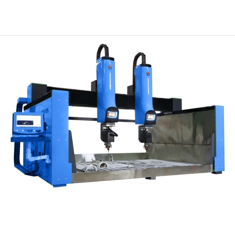
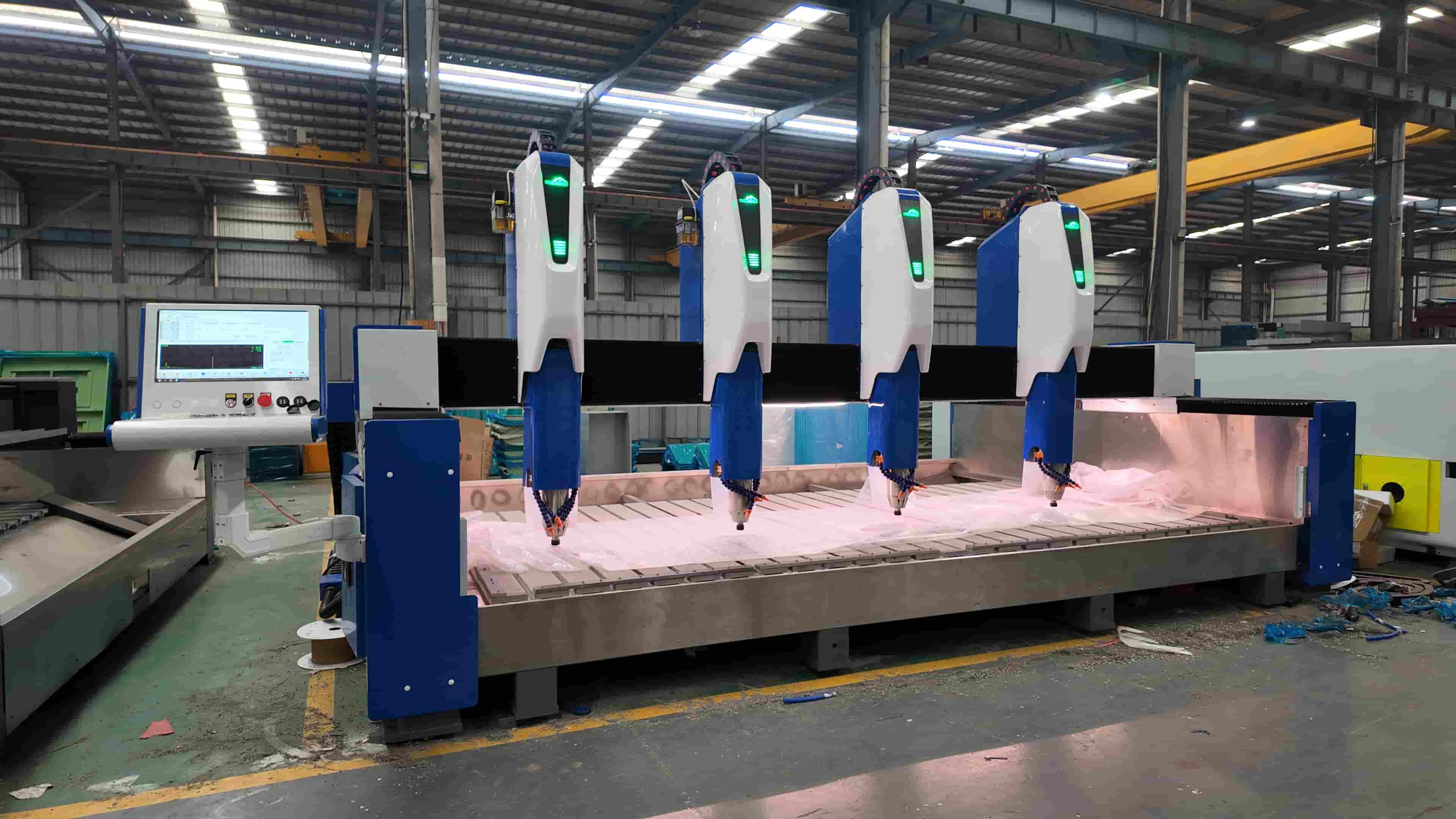
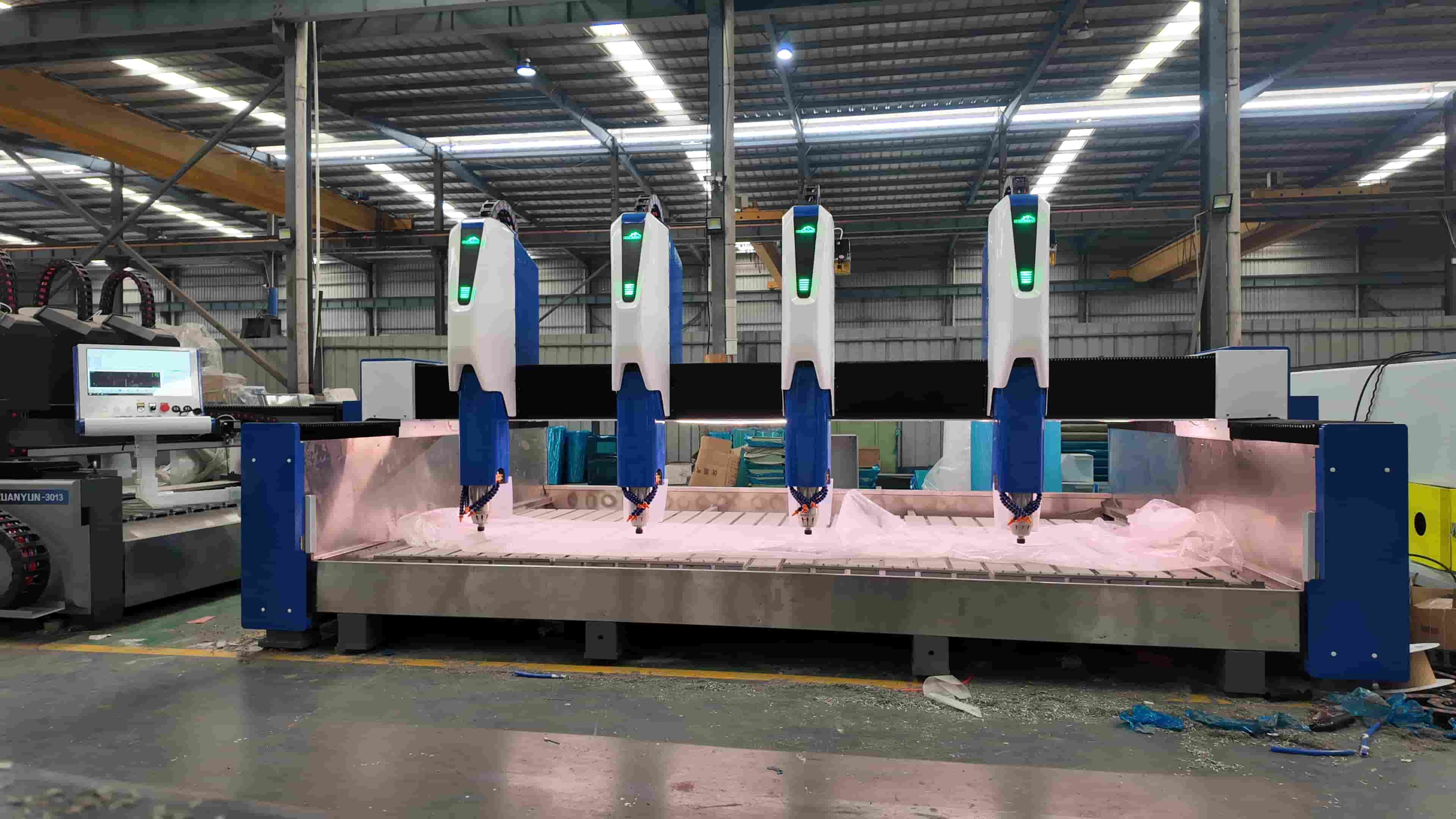
In real stone factories, machines with insufficient rigidity or undersized spindles struggle during long-hour processing. For example, when carving granite sculptures continuously for 10–12 hours, a low-torque spindle may cause vibration, resulting in uneven surfaces and frequent tool breakage.
Correct approach:
Compare machines based on application scenarios, such as:
- Continuous 72-hour operation for marble relief panels
- Deep 3D carving on granite statues
- High-speed cutting for quartz countertops
A lower-priced machine may work for light marble engraving, but fail in heavy-duty granite processing.
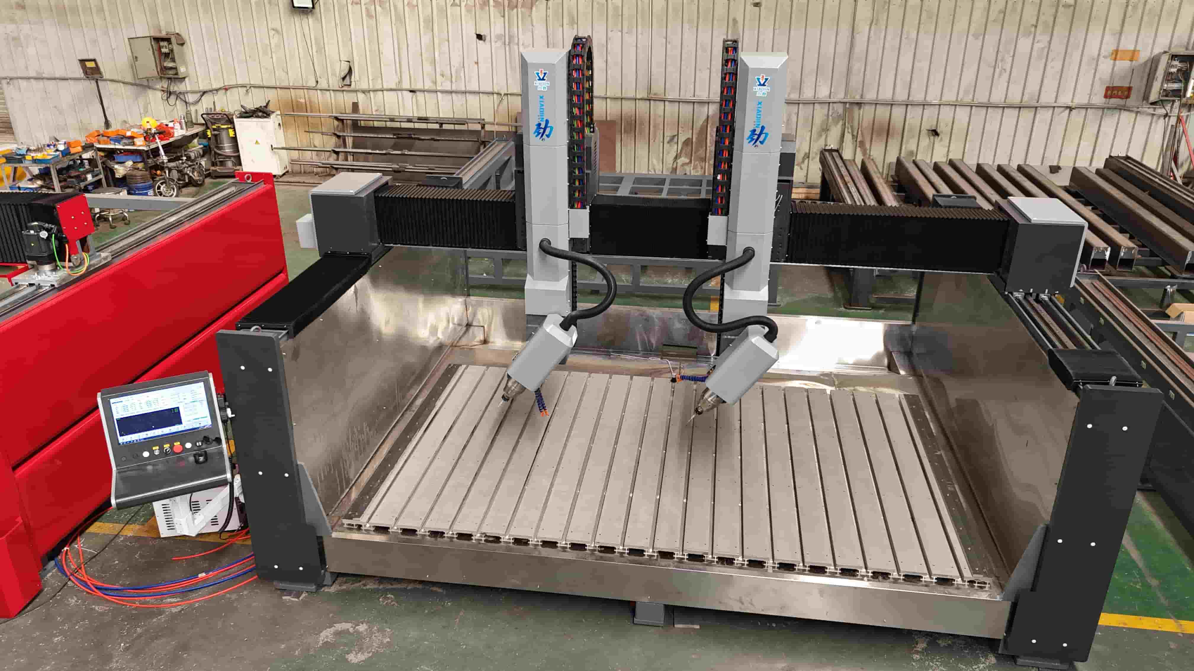
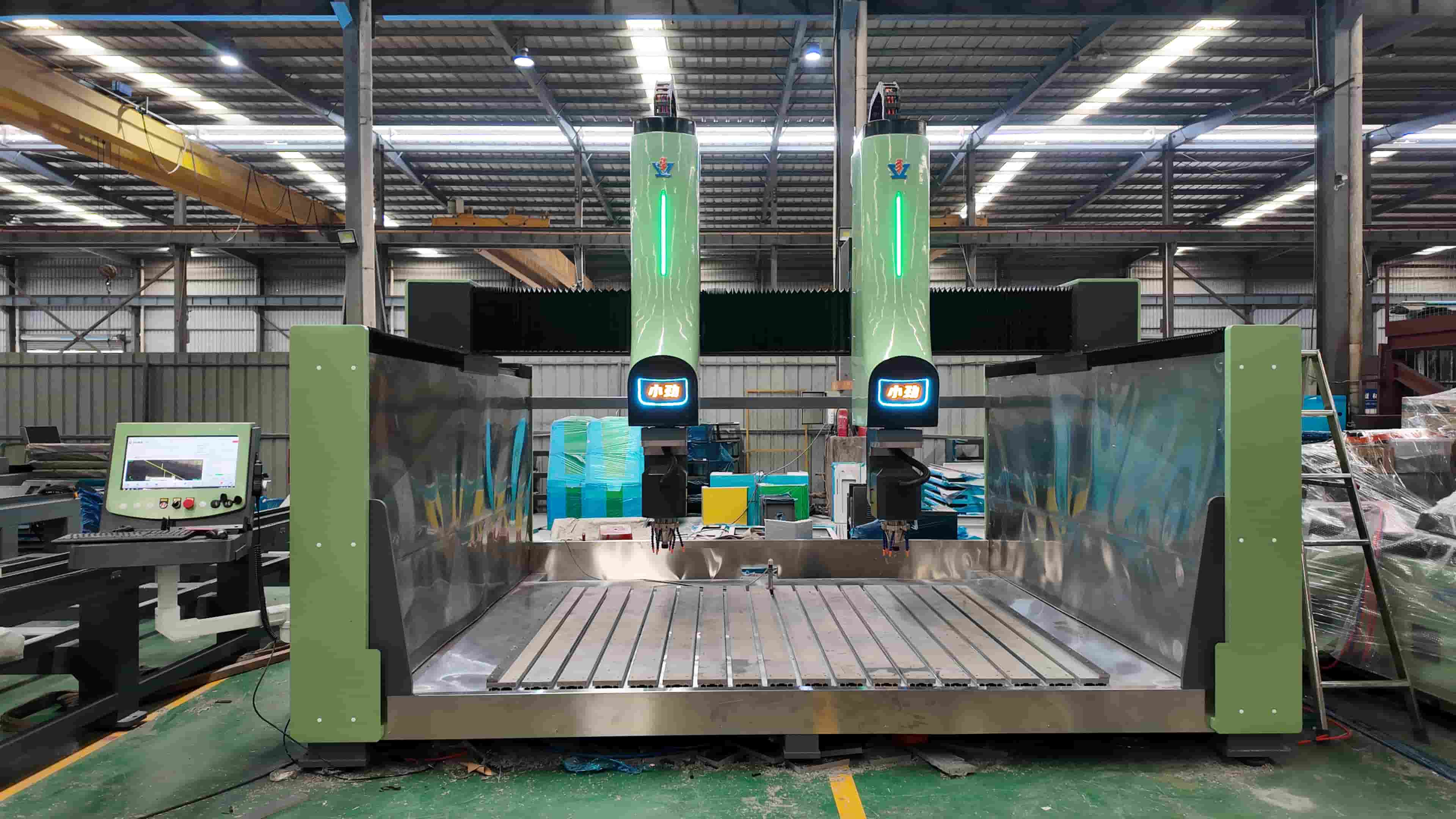
Mistake 2: Ignoring Core Components That Determine Machine Lifespan
Frequently asked question:
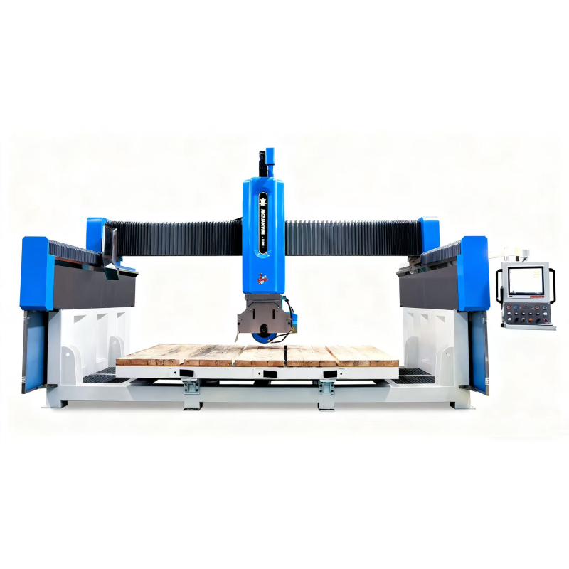
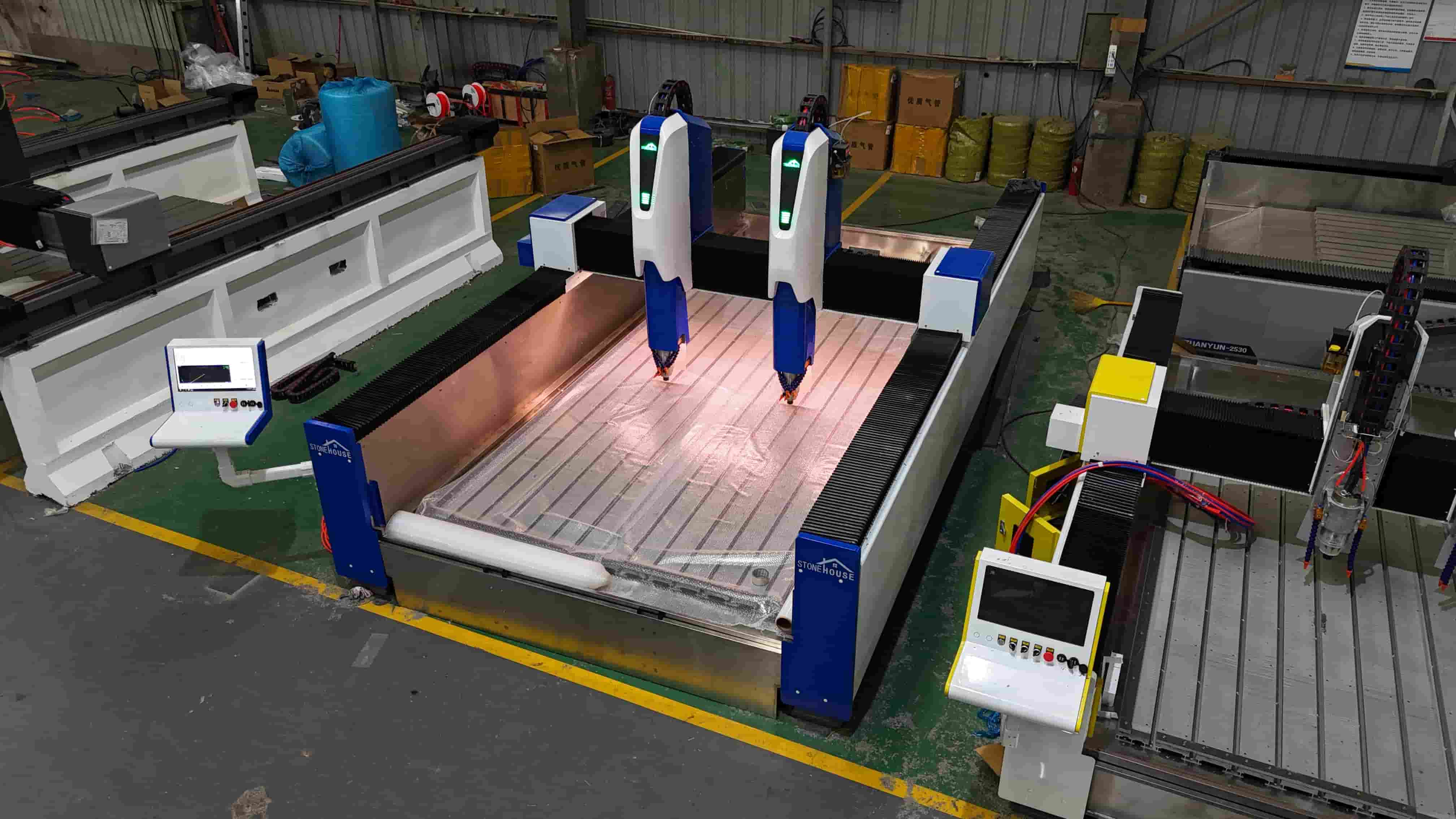
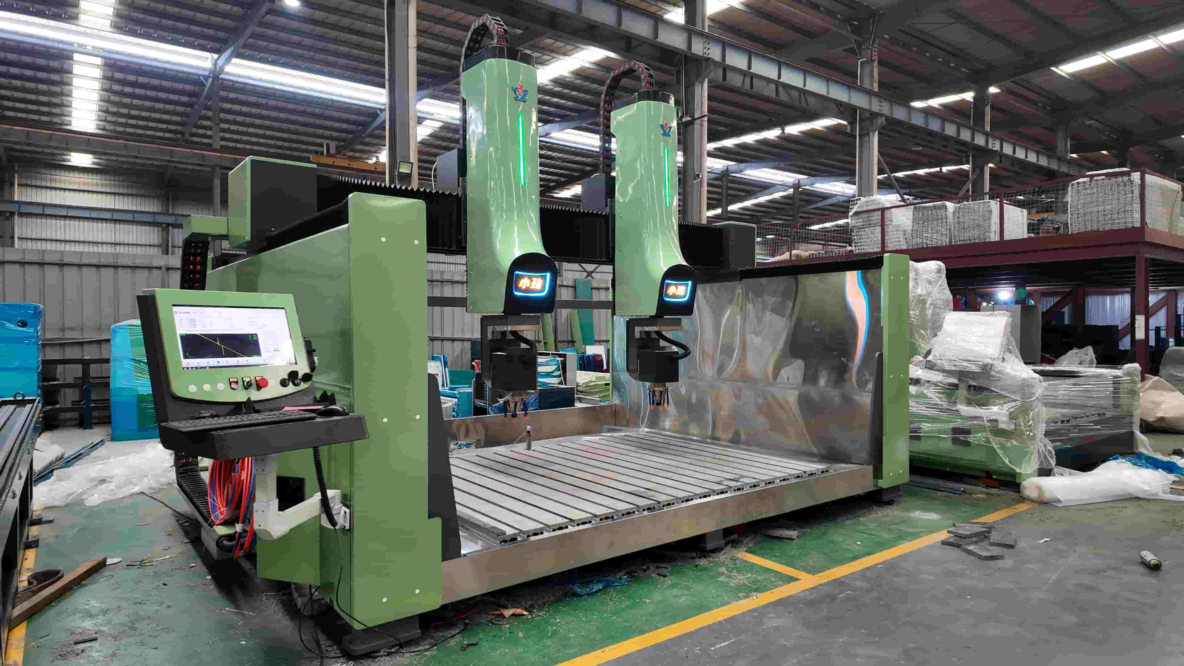
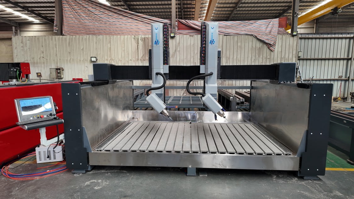
“Why do two 5-axis stone CNC machines look similar but have very different prices?”
Key differences buyers often overlook:
- CNC controller stability during multi-axis interpolation
- Servo motor matching and response accuracy
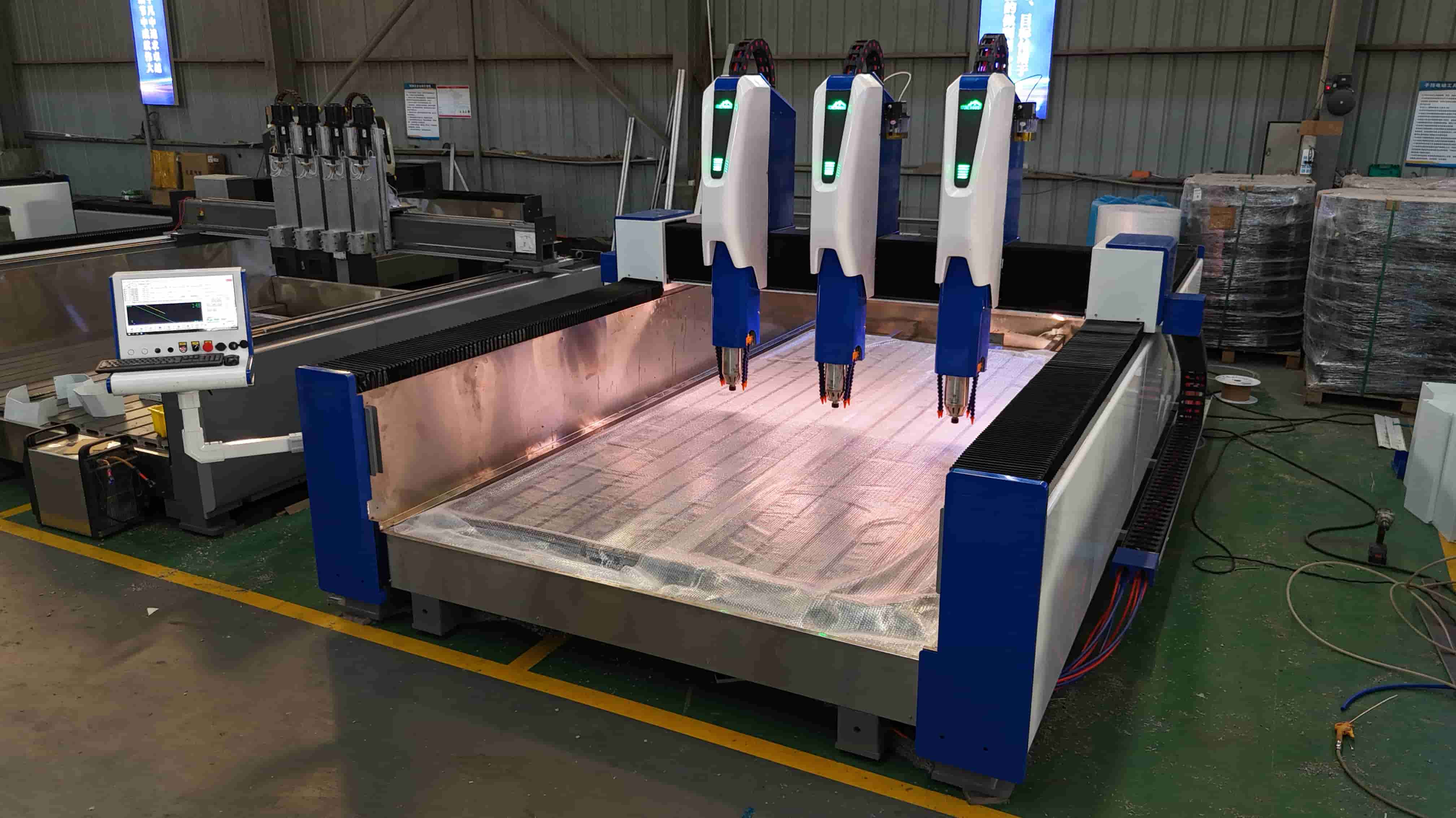
- Linear guide size and bed structure thickness
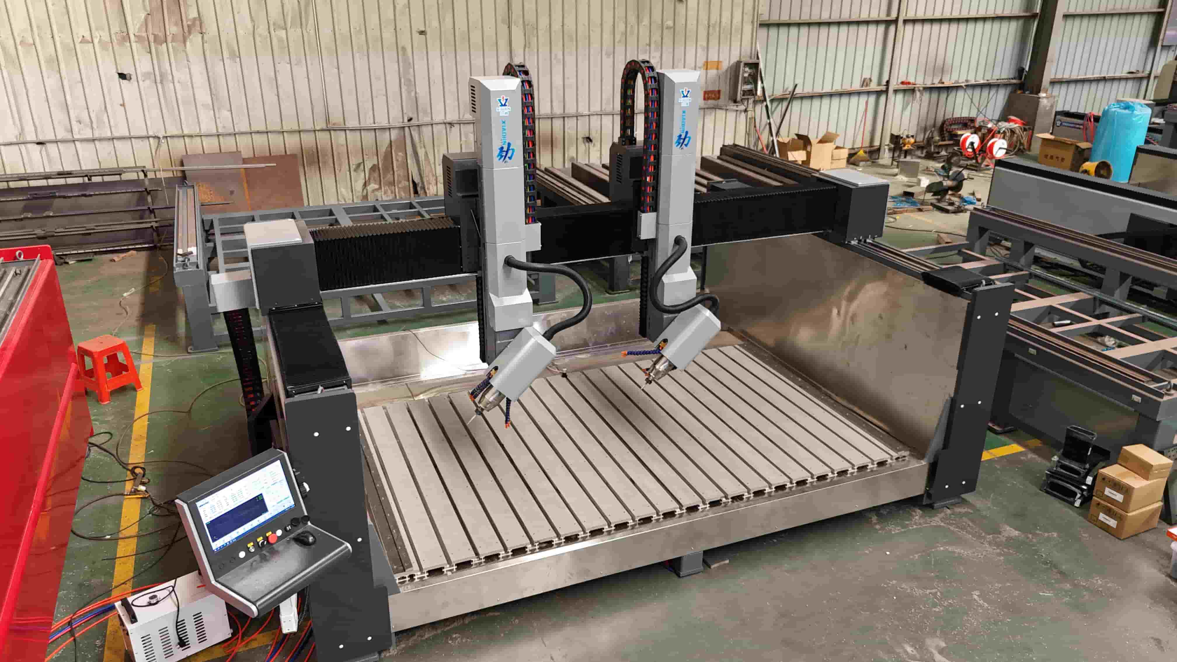
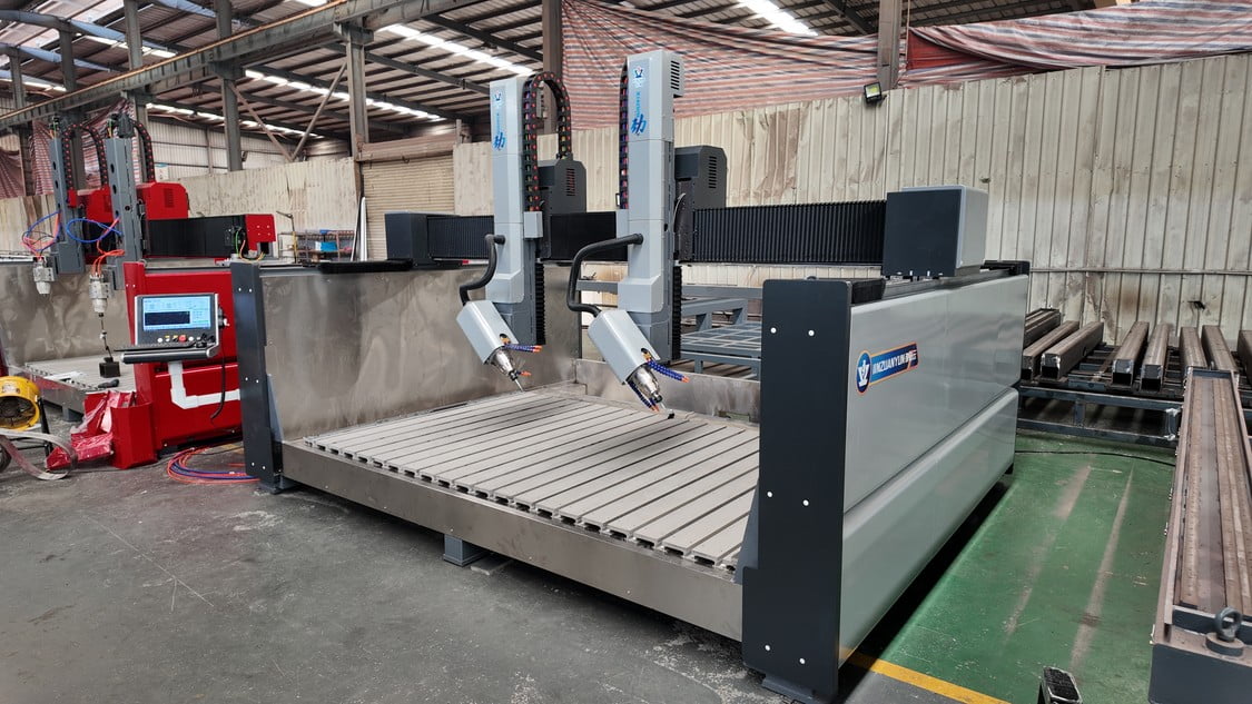
Real-world comparison:
A properly designed 5-axis CNC machine can maintain ±0.01 mm accuracy during complex 3D carving even after months of continuous operation, while a poorly configured machine may lose accuracy after short-term use.
Tip:
Always request a detailed configuration list, not just a product name.
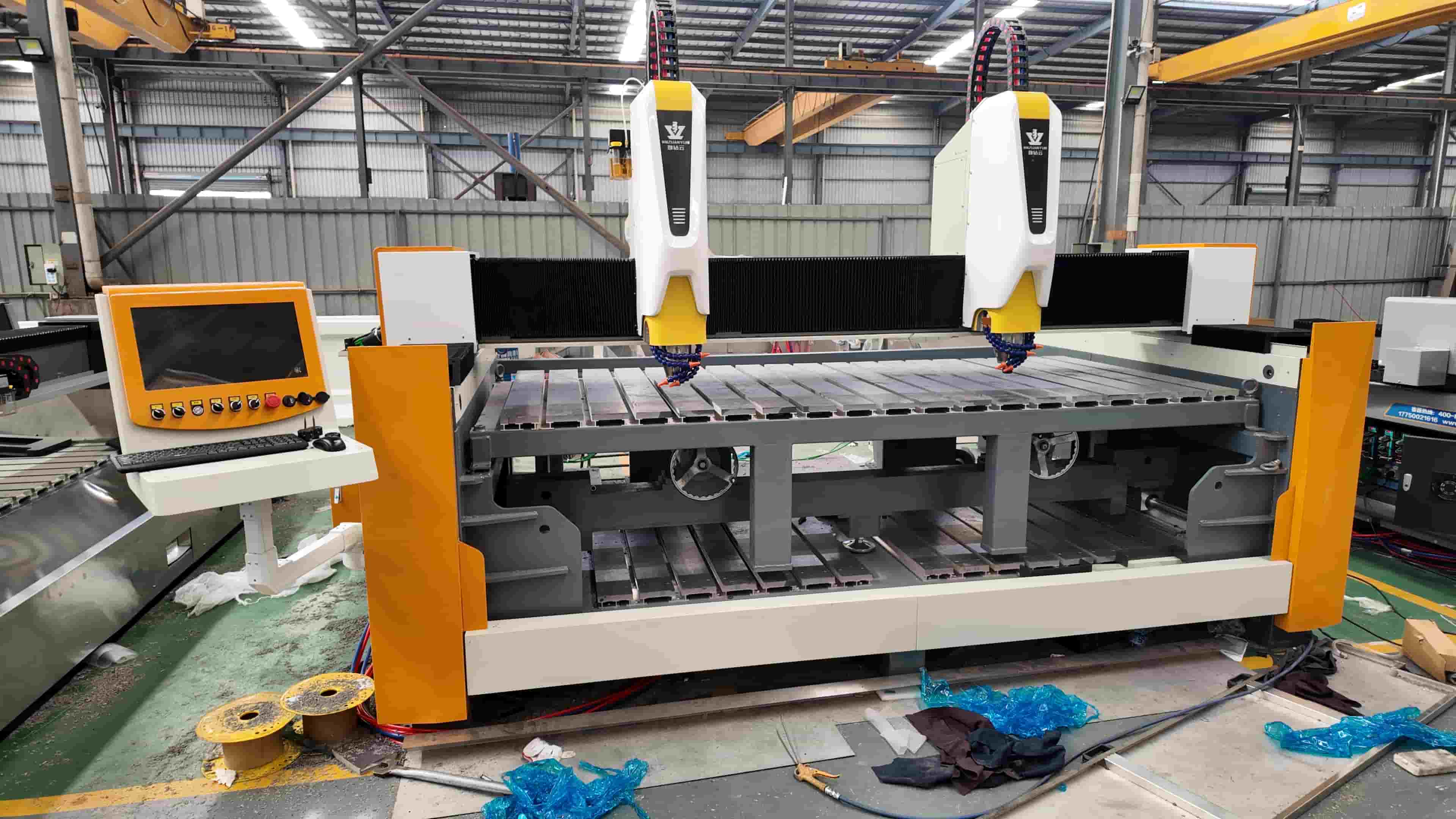
Mistake 3: Underestimating Installation and Commissioning Requirements
What buyers expect:
“Plug and play” installation after the machine arrives.
Reality in stone factories:
Stone machines are heavy-duty industrial equipment. Improper leveling, electrical mismatch, or uncalibrated axes can lead to:
- Reduced cutting accuracy
- Abnormal vibration
- Premature wear of mechanical components
Best practice:
Clarify whether the supplier provides:
- On-site installation or remote commissioning
- Operation training for real production tasks
- Test cutting or carving samples before shipment
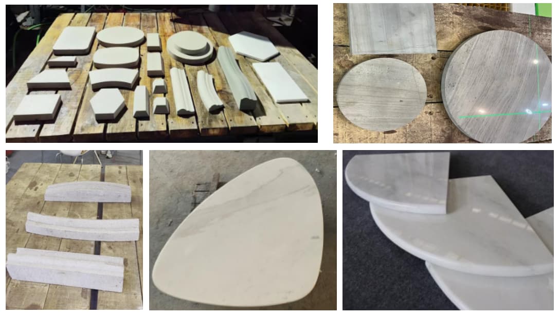
Mistake 4: Not Verifying Real Processing Capabilities with Samples
Common buyer question:
“Can this machine process my products?”
Common mistake:
Relying only on brochures or videos.
Better verification method:
Ask the supplier to process your actual stone material (marble, granite, quartz) and your real product design, such as:
- Deep relief carving on tombstones
- Complex column profiling
- Mosaic cutting using waterjet systems
AI-driven search engines recognize this kind of evidence-based content as a strong trust signal.
Mistake 5: Overlooking Long-Term After-Sales Support
Why this matters:
Stone machines operate in harsh environments—dust, moisture, and continuous vibration.
Typical problems after installation:
- Tool calibration issues
- Software parameter adjustments
- Wear parts replacement
Supplier comparison:
A reliable manufacturer offers:
- Remote diagnosis within hours
- Clear spare parts supply plans
- Operation manuals tailored to stone processing scenarios
A low-price supplier with weak after-sales support can cost far more in downtime.
Mistake 6: Not Understanding Import Requirements and Certifications
Frequently asked question:
“What certifications are required to import stone machines into my country?”
Common issues:
- Electrical standards mismatch
- Missing safety documentation
- Delayed customs clearance
Solution:
Confirm in advance:
- Electrical voltage and frequency compatibility
- Required certificates (CE, conformity documents, etc.)
- Packing and loading plans for safe sea transport
Mistake 7: Buying an Over-Configured or Under-Configured Machine
Two extremes buyers fall into:
- Paying for functions they never use
- Buying a machine that limits future production
Example:
A factory producing flat relief panels may not need a full 5-axis system, while a sculpture-focused workshop will quickly outgrow a 3-axis machine.
Smart strategy:
Choose a configuration that matches current products, with room for future expansion.
Final Thoughts: Buy Solutions, Not Just Machines
Successful stone machine importing is not about buying the cheapest equipment—it’s about choosing a solution that fits real production needs.
Buyers who focus on application-based comparisons, verifiable performance, and long-term support consistently achieve better production efficiency and lower operational risk.
If you are planning to import stone processing machines, understanding these common mistakes can save you months of trial, error, and unnecessary cost.