What Is an Environmental Test Chamber and How Is It Used in Product Development?

1. Basic Introduction to Environmental Chambers

An environmental test chamber is a sealed experimental device capable of precisely simulating various natural or extreme environmental conditions (such as temperature, humidity, air pressure, lighting, gas composition, vibration, radiation, etc.). Its core function is to provide controlled and repeatable environmental scenarios for products or materials, enabling the evaluation of their performance, stability, durability, safety, and other critical metrics under different environmental conditions. It is widely used in product development, quality testing, scientific research experiments, and other fields, serving as an “environmental simulation laboratory” for verifying product reliability.
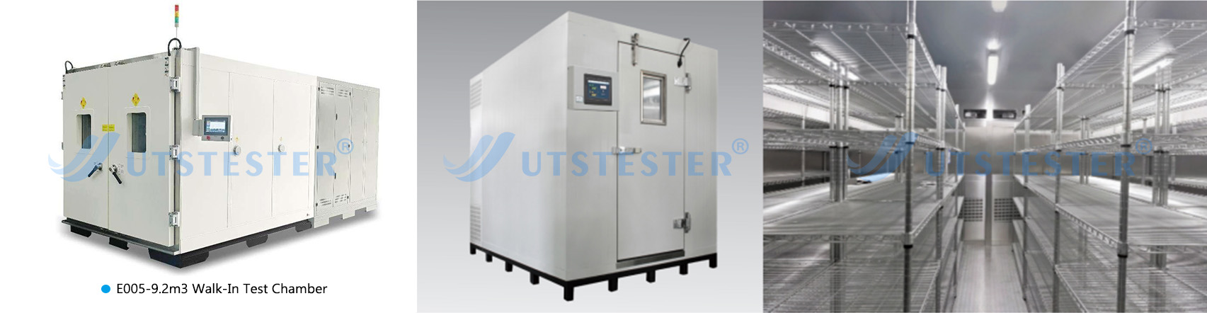
Environmental Testing Equipment


2. Structural Composition of the Environmental Chamber

(1)Control System: Includes control modules for temperature, humidity, lighting, gas concentration, etc., serving as the “brain” of the environmental chamber, responsible for setting, monitoring, and controlling environmental parameters.

(2)Test Chamber: Constructed from high-strength, corrosion-resistant materials, it features excellent sealing and insulation properties, with an adjustable internal space designed to accommodate test samples.

(3)Heating and Cooling System: Enables rapid temperature changes and stable control within the chamber, ensuring the accuracy of the test environment.

(4)Humidity Control System: Utilizes humidification and dehumidification devices to precisely control humidity levels within the chamber, meeting various testing requirements.

(5)Circulation System: Ensures uniform distribution of environmental parameters within the chamber, enhancing the reliability and accuracy of testing.

(6)Monitoring System: Continuously monitors environmental parameters inside the chamber to ensure environmental stability and provide reliable data support for testing.

(7)Alarm System: Issues an alarm signal when environmental parameters exceed the set range, promptly alerting users to ensure safe testing operations.


3. Environmental Chamber Usage Process

When using an environmental chamber for testing, the following process should generally be followed:

(1)Preparation: Inspect all components of the equipment to ensure they are in good condition and that cable connections are secure; clean the interior of the test chamber to ensure no debris affects test results; verify that parameters in the control system are correctly set; place the product to be tested into the environmental simulation chamber.

(2)Set Test Conditions: Based on test requirements, use the control panel to set parameters such as temperature, humidity, lighting, and gas concentration; activate the cooling or heating system to adjust the internal temperature to the desired level; activate the ventilation system to maintain airflow within the chamber.

(3)Begin testing: After setting the test conditions, the environmental testing of the product can commence. Throughout the testing process, closely monitor changes in internal parameters such as temperature and humidity, and promptly adjust relevant parameters in the control system to ensure accurate and reliable test results.



4. Application Cases for Environmental Chambers

(1) When developing an outdoor smartwatch, it is necessary to test its screen display, battery life, and sensor sensitivity under extreme conditions of -30°C (extreme cold) and 60°C (high temperature) in a high/low-temperature test chamber. Additionally, the material of the watch strap must be verified in a humid heat test chamber to ensure it does not crack or mold due to high humidity (90% RH).

(2) Medical devices (such as infusion sets) must undergo sterilization compatibility testing in accordance with ISO 11607 standards. This involves simulating the sterilization process in a high-temperature, high-pressure steam test chamber to verify whether the materials deform or experience performance degradation due to high temperatures.

(3) For special industries (such as aerospace, defense, and polar research), environmental test chambers must simulate extreme environments to verify product reliability under “non-routine conditions.”


Email: hello@utstesters.com

Direct: + 86 152 6060 5085

Tel: +86-596-7686689

Web: www.utstesters.com
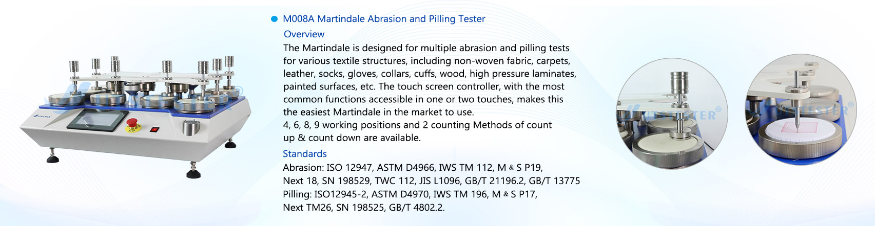
What is the Martindale Abrasion Test?

The Martindale Abrasion Test is a test of textile products using the Martindale standard system to determine the abrasion resistance of a fabric. Abrasion resistance refers to a fabric's resistance to repeated friction with other materials. Pilling resistance is a key quality indicator of textile products, directly impacting their durability and performance. The Martindale Abrasion Tester is used to test a fabric's abrasion and pilling resistance.

1. Martindale Test Standards

Because different countries and regions have different standards, we can categorize them into international standards, US standards, European standards, and Chinese standards. Details are as follows:

1.1International Standards

ISO 12947.2—1998 Martindale Test for Fabrics — Part 2: Measurement of Specimen Damage

ISO 12947.3—1998 Martindale Test for Fabrics — Part 3: Measurement of Mass Loss

ISO 12947.4—1998 Martindale Test for Fabrics — Part 4: Measurement of Appearance Change

1.2American Society for Materials (ASTM)

ASTM D4966-2010

1.3EU Standards

EN ISO 12947.2-1998 - Determination of fabric resistance to abrasion and pilling by the Martindale method - Part 2: Measurement of specimen breakage

EN ISO 12947.3-1998 - Determination of fabric resistance to abrasion and pilling by the Martindale method - Part 3: Measurement of mass loss

EN ISO 12947.4-1998 - Determination of fabric resistance to abrasion and pilling by the Martindale method - Part 4: Measurement of appearance change

1.4Chinese Standards

GB/T 21196.2-2007 - Determination of fabric resistance to abrasion and pilling by the Martindale method - Part 2: Measurement of specimen breakage

GB/T 21196.3-2007 - Determination of fabric resistance to abrasion and pilling by the Martindale method - Part 3: Measurement of mass loss

GB/T 21196.4-2007 - Determination of fabric resistance to abrasion and pilling by the Martindale method - Part 4: Determination of appearance change


2. How is the Martindale Wear Test performed?

2.1 Preparation: Check the instrument status and prepare the specimen and sandpaper.

2.2 Specimen Installation: Secure the specimen in the specimen fixture and adjust the contact force between the specimen and the sandpaper.

2.3 Test Parameter Settings: Set the rotational speed, wear load, and other parameters according to the test requirements.

2.4 Test Start: Start the instrument, perform the wear test, and record the specimen wear.


3.Note: The standard friction cloth should be replaced before testing each new sample or after 50,000 cycles. Check the standard friction cloth for contamination or wear and replace if necessary. This method is not suitable for fabrics thicker than 3mm. Samples may be washed or dry-cleaned before testing.


4. Test Results Evaluation Methods

There are three Martindale methods for evaluating fabric abrasion resistance: the specimen breakage method, the mass loss method, and the appearance quality change method. The specimen breakage method is the most commonly used of the three methods, as it offers minimal error, intuitive and clear test results, and facilitates comparison of the abrasion resistance of different fabrics. The mass loss method and the appearance quality change method are more complex to evaluate, but they can reflect the abrasion resistance of a sample at different stages of friction. They are highly practical for manufacturers and research institutions in analyzing fabric usage.


Email: hello@utstesters.com

Direct: + 86 152 6060 5085

Tel: +86-596-7686689

Web: www.utstesters.com


Alligator Shear The Heavy-Duty Metal-Cutting Machine

Alligator shears are powerful hydraulic machines widely used in metal recycling and fabrication industries. Shaped like an alligator's open jaws, their large, sharp blades can cut through various metals, including steel, iron, aluminum, copper, and even reinforced bars, with ease and precision.


These shears operate on a simple yet effective principle. A robust hydraulic system generates high-pressure force, driving the upper blade down onto the metal placed on the fixed lower blade. The powerful shearing action cleaves through the material quickly and cleanly, reducing it into smaller, more manageable pieces with minimal deformation.


Their applications are diverse and critical across multiple sectors. In scrapyards and recycling centers, alligator shears break down large metal scraps such as beams, pipes, and car parts, optimizing storage, transportation, and melting efficiency. In manufacturing and metal fabrication, they are used to cut metal rods, strips, and plates into specific sizes for further processing. Construction sites also employ these shears for rebar and structural steel cutting.


Key advantages include enhanced safety features such as overload protection valves to avoid machine damage, and durable blades made from high-grade alloy steel that retain sharpness over prolonged use. Their simple structure allows for easy maintenance and low operational costs.


By automating one of the most labor-intensive steps in metal processing, alligator shears significantly enhance workflow efficiency, reduce manual labor, and improve the overall productivity and safety of metal-handling operations. Thanks to their reliability, rugged construction, and cutting-edge hydraulic technology, alligator shears remain essential tools in modern metalworking.

Container Shear Buying Guide

In the demanding sectors of demolition and scrap processing, maximizing productivity while maintaining safety is the ultimate goal. The container shear has rapidly become a critical tool in achieving this objective, offering a powerful and versatile solution for material reduction.


The container shear’s uniquely designed jaws deliver immense cutting power, capable of cleanly shearing through thick steel, structural beams, automobiles, and mixed industrial scrap. This ability to process diverse materials makes it an incredibly valuable asset on any job site.


The advantages of integrating a container shear into your operations are clear. It dramatically increases productivity by reducing large, unwieldy items into compact, manageable loads in minimal time. This efficiency not only speeds up project cycles but also optimizes transportation and storage space, leading to significant cost savings. Furthermore, by streamlining the size reduction process, it produces higher-quality, contaminant-free scrap, which can increase its value in the recycling market. From a safety perspective, the mechanized cutting process reduces reliance on manual torching or unpredictable demolition methods, creating a more controlled and safer working environment.


Choose a container shear that suits you, the following points are very important

1. Cutting Force:

Usually measured in tons (Tons) or kilonewtons (kN). This is the core metric for measuring a shear's capacity, ranging from several hundred tons to thousands of tons. The greater the cutting force, the thicker and harder the material it can handle.


2. Cutting Length:

This determines the width of material that can be cut at a time. Common sizes range from 600mm to 2000mm or even longer.


3. Feed Opening Size:

The width and height determine the size of the scrap you can handle. If you frequently process large scrap, you'll need a wide and tall feed opening.


4. Main Cylinder Pressure and Motor Power:

These two factors together determine shear force and operating speed. Higher power generally results in faster cycle times and higher efficiency.


5. The required production capacity:

How many tons of material do you need to process per hour/day/month? This is the most critical factor in determining the type (size) of equipment. Production capacity directly impacts the price.


6. Cycle Time:

The time required to complete one cycle of "press, shearing,push out,back." The shorter this time, the higher the theoretical production capacity.


More than just a powerful tool, the container shear is a strategic investment. It enhances operational capabilities, improves profitability, and sets a new standard for efficiency in demolition and recycling. Embracing this technology is key to building a more productive and competitive future.


Metal Gantry Shearing Machine Precision and Efficiency in Metal Fabrication

In modern industrial manufacturing, metal processing requires high precision and efficiency to meet the demands of various industries. The metal gantry shearing machine stands out as a crucial piece of equipment in metal fabrication, offering superior cutting performance, durability, and automation capabilities. This article explores its features, applications, and advantages in industrial settings.


What Is a Metal Gantry Shearing Machine?

A gantry shearing machine is a heavy-duty cutting device designed to shear metal sheets with high accuracy. Unlike traditional guillotine shears, it utilizes a gantry-style frame for enhanced stability and cutting force. The machine typically consists of a robust frame, hydraulic or mechanical drive system, adjustable blade clearance, and an advanced control panel for precise operation.


Key Features and Working Principle

1. High-Strength Gantry Structure – The gantry design ensures rigidity, reducing vibration and deformation during cutting, which is essential for maintaining precision in thick metal sheets.

2. Hydraulic or Servo-Driven System – Hydraulic models provide powerful shearing force, while servo-driven versions offer faster, energy-efficient operation with programmable controls.

3. Adjustable Blade Clearance – Operators can set the gap between the upper and lower blades to accommodate different material thicknesses, ensuring clean cuts without burrs.

4. CNC and Automation Integration – Advanced models feature CNC controls, allowing for automated cutting sequences, reducing manual intervention, and improving repeatability.


The machine works by clamping the metal sheet in place before the descending blade applies shear force, cleanly separating the material along a straight line.


Applications in Industry

Metal gantry shearing machines are widely used in:

· Automotive Manufacturing – Cutting steel plates for car frames and body parts.

· Shipbuilding – Processing large metal sheets for hull construction.

· Construction & Infrastructure – Fabricating structural steel beams and panels.

· Aerospace & Defense – Precision cutting of high-strength alloys.


Advantages Over Traditional Shears

· Higher Cutting Capacity – Capable of handling thicker and harder metals (up to 30mm or more, depending on the model).

· Improved Accuracy – The gantry frame minimizes deflection, ensuring straight cuts even under heavy loads.

· Energy Efficiency – Servo-driven models reduce power consumption compared to hydraulic alternatives.

· Safety & Automation – Equipped with safety guards and programmable controls to minimize operator risks.


The metal gantry shearing machine is a vital tool in modern metalworking, combining strength, precision, and automation to enhance productivity. As industries demand higher-quality cuts with minimal waste, these machines will continue to evolve with smarter controls and improved efficiency. Whether for large-scale fabrication or specialized metal processing, investing in a high-performance gantry shear ensures long-term reliability and cost-effectiveness.

The Briquetting Machine Turning Waste into Value

A briquetting machine compresses loose (often waste) materials into compact solid briquettes. This process, briquetting, is a form of densification that reduces the material's volume, making it easier to handle, transport, and store. The core principle is to apply great pressure to the raw feedstock, binding it together usually without external adhesives.


Briquetting machines have diverse applications. In agriculture, they convert residues like sawdust and straw into clean-burning fuel. Metalworking industries use them to compress chips into dense, recyclable briquettes, saving space and reducing oxidation. Even household paper waste can be compacted into useful kindling.


The benefits of using a briquetting machine are substantial. First, it offers a waste management solution, converting waste into a valuable commodity and promoting a circular economy . Second, the briquettes are a more efficient and eco - friendly fuel than traditional fossil fuels. For businesses, briquetting can save costs by reducing waste disposal fees and generate new revenue from selling the briquettes.


In conclusion, the briquetting machine is a simple but effective technology with notable economic and environmental benefits. It transforms bulky, low - value waste into dense, usable briquettes, thus playing a key role in promoting sustainability, enhancing efficiency, and adding value in various sectors. 

The Heavy Metal Shredder Machine Power and Efficiency in Industrial Recycling

In today’s industrial landscape, the demand for efficient waste management and metal recycling has led to the development of advanced machinery like the heavy metal shredder machine. This powerful equipment plays a crucial role in processing scrap metal, reducing waste volume, and preparing materials for recycling. With its robust design and high-performance capabilities, the heavy metal shredder is an indispensable tool in modern recycling facilities.


What is a Heavy Metal Shredder Machine?

A heavy metal shredder is a large-scale industrial machine designed to break down bulky metal waste into smaller, manageable pieces. It can process various materials, including steel, aluminum, copper, and even electronic waste (e-waste). The shredded output is easier to transport, sort, and melt down for reuse, making the recycling process more efficient and cost-effective.


Key Features and Working Principle

1. Durable Construction – Built with high-strength steel and wear-resistant components, these shredders withstand extreme stress and prolonged operation.

2. Powerful Motor & Blades – Equipped with high-torque motors and hardened cutting blades, they can crush thick metal sheets, car parts, and industrial scrap effortlessly.

3. Hydraulic or Electric Drive Systems – Depending on the model, shredders use hydraulic pressure or electric motors to deliver consistent shredding power.

4. Safety Mechanisms – Advanced models include overload protection, emergency stops, and automatic reversal to prevent jams and damage.


The shredding process involves feeding scrap metal into the machine, where rotating blades or hammers tear it apart. The shredded material is then sorted, either magnetically (for ferrous metals) or through air separation (for non-ferrous metals).


Applications of Heavy Metal Shredders

· Automotive Recycling – Shredding end-of-life vehicles (ELVs) to recover steel, aluminum, and other metals.

· Industrial Scrap Processing – Handling manufacturing waste, machinery parts, and construction debris.

· E-Waste Recycling – Breaking down old electronics to extract valuable metals like gold, silver, and copper.

· Metal Smelting Preparation – Reducing large metal pieces into uniform fragments for easier melting.


Benefits of Using a Metal Shredder

· Cost Savings – Reduces transportation and storage costs by compacting waste.

· Environmental Impact – Promotes metal recycling, reducing landfill waste and conserving natural resources.

· Energy Efficiency – Recycled metal requires less energy to process than virgin ore.

· Versatility – Can handle a wide range of metal types and sizes.


Future Trends in Metal Shredding Technology

As sustainability becomes a global priority, shredder manufacturers are focusing on:
✔ Automation & AI Integration – Smart shredders with sensors for real-time monitoring.
✔ Higher Efficiency Designs – Improved blade technology and energy-saving motors.
✔ Eco-Friendly Processing – Reducing emissions and noise pollution during operation.


The heavy metal shredder machine is a cornerstone of modern recycling, offering unmatched efficiency in processing scrap metal. With continuous advancements in technology, these machines will play an even greater role in sustainable industrial practices. Whether for automotive, manufacturing, or e-waste recycling, investing in a high-quality shredder ensures long-term economic and environmental benefits.


By embracing this technology, industries can contribute to a circular economy—where metal waste is transformed into valuable resources rather than ending up in landfills. The future of recycling is shredding forward!

The Vertical Baler Compacting Waste Efficiently and Safely

In the world of waste management and recycling, efficiency, space optimization, and safety are paramount. The vertical baler stands as a workhorse solution, specifically designed to compact loose, bulky materials into dense, manageable bales. As its name suggests, this machine operates with a vertically oriented hydraulic ram that delivers powerful downward force.


Core Function and Operation:

1.  Loading: Operators feed loose materials (cardboard, plastic film/fabric, paper, OCC, non-ferrous metals, textiles) through an open top or large side door into the main compression chamber.

2.  Compression: Once loaded, the machine is activated (usually via control panel buttons). A heavy-duty hydraulic ram descends from the top of the chamber, exerting immense pressure (often measured in tons) to crush and compress the material downwards against a fixed baseplate.

3.  Bale Formation: This cycle repeats. Material is added, compressed, added again, and compressed further. Guides within the chamber ensure the material forms a neat rectangular block.

4.  Ejection: When the bale reaches the desired size and density (often signaled by a pressure gauge or automatic cycle counter), the compression stops. A door (typically on the front or side) opens, and the bale is ejected – sometimes manually pushed out, often assisted by the rising ram or a separate ejection mechanism. The bale is then strapped or wired for handling and transport.


Key Advantages:

   Space Efficiency: Vertical balers have a significantly smaller footprint than their horizontal counterparts. This makes them ideal for facilities where floor space is at a premium – retail stores, supermarkets, warehouses, distribution centers, manufacturing plants, and smaller recycling depots. They often fit neatly into stockrooms or dock areas.

   Lower Initial Cost & Operating Cost: Generally less expensive to purchase and install than horizontal balers. They also tend to have simpler hydraulic systems, potentially leading to lower maintenance costs.

   Ease of Operation & Safety: Loading is straightforward, often done at waist or chest height, reducing bending and heavy lifting before compaction. Modern models feature extensive safety interlocks (guards, two-hand operation, door locks) preventing operation while doors are open, significantly enhancing operator safety compared to less controlled compaction methods.

   Versatility: While exceptionally effective for high-volume cardboard (OCC) and plastic film (LDPE stretch wrap, bags), they handle a wide range of lightweight, bulky recyclables and waste streams effectively.

   Reduced Hauling Costs & Increased Revenue: Compacting waste dramatically reduces its volume. This means fewer pickups by waste haulers (saving on service fees) and denser, higher-quality bales that fetch better prices from recyclers.


Common Applications:

   Retail & Grocery: Cardboard boxes, plastic packaging, plastic bags.

   Warehousing & Distribution: Shipping cartons, filler materials, plastic wrap.

   Manufacturing: Off-cuts, packaging waste, non-hazardous scrap.

   Office Complexes: Confidential paper waste, bulk paper/cardboard.

   Recycling Centers: Pre-compaction of specific streams before further processing.


The vertical baler is an indispensable tool for businesses and facilities generating significant volumes of lightweight, bulky recyclables and waste. By offering a compact footprint, relatively low cost, safe operation, and the ability to dramatically reduce waste volume, it delivers tangible benefits: lower disposal costs, potential revenue from recyclables, cleaner workspaces, and more efficient waste handling logistics. Its vertical compression action provides a practical and economical solution for achieving efficient waste compaction where space is limited.

Application of hand-held drone countermeasures equipment in ad hoc activities

         Handheld Drone Countermeasures Equipment in Temporary Events,With the advancement of science and technology, drone technology is becoming increasingly popular, and its application in aerial photography, logistics, agriculture and other fields is becoming more and more widespread. However, the misuse of drones has also brought about security risks, especially in large-scale temporary events, where unauthorized drones may interfere with the order of the event or even threaten public safety. Handheld drone countermeasure equipment has become an important tool for dealing with drone threats at temporary events due to its portability and efficiency.


         Handheld drone countermeasures devices typically employ techniques such as radio jamming, navigation signal spoofing or directed energy, and are capable of forcing a drone to land, return to flight or lose control in a short period of time. Their compact size and easy operation make them suitable for security personnel to respond quickly to unexpected situations during temporary events. For example, in large-scale performances, sports events or important meetings, security personnel can hold the device to accurately counteract suspicious drones to ensure that the activities are carried out in a safe and orderly manner.


         The potential threat of drones cannot be ignored during impromptu events. Unauthorized drones may carry camera equipment that violates privacy, fall and injure people due to improper operation, or even be maliciously exploited for anti-terrorist attacks. Traditional means of defense and control, such as early warning radar or fixed jamming equipment, are often difficult to meet the needs of temporary activities due to long deployment cycles and high costs. Handheld drone countermeasure equipment, on the other hand, does not require complex installation and can be put into use at any time, thus making up for this shortcoming.


         In addition, the application of hand-held drone countermeasures needs to comply with relevant laws and regulations to avoid interfering with legitimate drone communications. Operators need to be professionally trained to ensure precise use when necessary, while reducing the impact on the surrounding electromagnetic environment. In temporary activities, the reasonable delineation of no-fly zones for drones and the use of countermeasure equipment can form a three-dimensional prevention and control system, significantly enhancing the level of security.


         In conclusion, hand-held drone countermeasures equipment, with its flexible and efficient features, has become an ideal choice for dealing with drone threats in ad hoc activities. In the future, with the further improvement of technology, such equipment will play an even more important role in the field of public security.


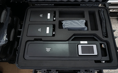
         Clairvoyant Aerial Drone Countermeasures Equipment F90S, characterized by small size, light weight, easy to handheld work, can be activated at any time to work. External battery can reduce the weight of the device itself, light to carry and more convenient battery replacement. The new touch screen design and the newly added password power on function make the operation more convenient. The device can carry out directional countermeasures management for drones in an all-round way, thus making them lose the flight control instructions and satellite positioning information and unable to fly normally, and achieving the control effect of forced landing and driving away of the black-flying drones.


Precautions


         The drone countermeasures equipment should be charged in time when it is used to the low battery alarm state, and try to avoid entering into the state of power loss.


  Avoid strong collision and fall when using, and put it into the protective box when not in use.


  After long-term use of the device, the buttons and the casing will become dirty easily, please use neutral detergent and a damp cloth to clean the casing. Do not use chemicals such as detergents, alcohol, sprays or petroleum agents that may cause damage to the equipment.


  Ensure that the equipment is away from sources of ignition while also ensuring that the contact environment is dry, do not allow the battery to come into contact with water, otherwise there is the possibility of a short-circuit situation.


Warm tips:

         In recent years, professional-grade and consumer-grade drones have shown explosive development trends around the world, and while the industry is developing at a rapid pace, the phenomenon of black flights of drones is rife, and safety incidents occur from time to time. In order to standardize drone flight activities and promote the steady development of the drone industry.

Assembling plant protection drone graphic details

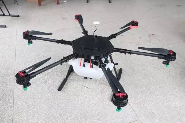
         The article begins with an emphasis: plant protection is risky, choose carefully! It is not recommended that private individuals without drone experience assemble plant protection drones on their own. Assembling a drone requires three points of skill and seven points of care, welding and debugging are the two main points, and you need to have enough skill and care before you can achieve the right result. We hope that all of you will get this secret book and practice it carefully, so that you will be able to assemble the drone as soon as possible.

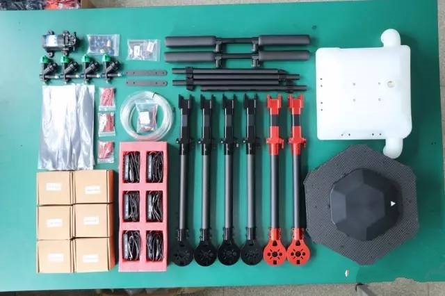
1、Material preparation


  Material list:


  1. Frame: EFT 6-axis 10kg frame


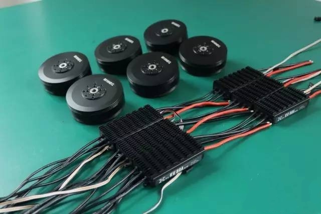
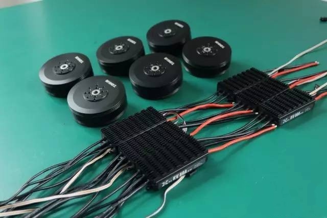
  2. Power system: 6 8010 motors, 80A ESC, 3 pairs of 24-inch folding paddles.


  3. Spray system: 1 water pump, 1 ESC, 4 pressure nozzles, water pipes and adapters


  4. Flight control: DJI A3 (mounting reference)


  5. Plug accessories: AS150 anti-ignition male red and black 2 pairs, XT90 male 6, XT60 male and female head 1 pair, 4.0mm banana head male and female 18 pairs, 5mm heat-shrinkable tubing 1 meter, 10mm heat-shrinkable tubing 1 meter, 8mm snakeskin mesh tube 4 meters


  6. Tools: a set of hexagonal screwdriver, more than 150W soldering station 1, 1 hot air gun


2、Installation of the rack


  Rack factory are modular, has completed most of the internal assembly, so the overall installation is relatively simple, the factory comes with a manual, you can refer to the instructions for assembly.


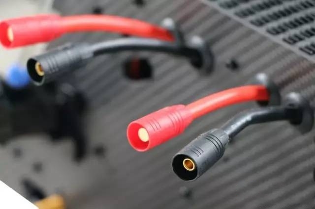
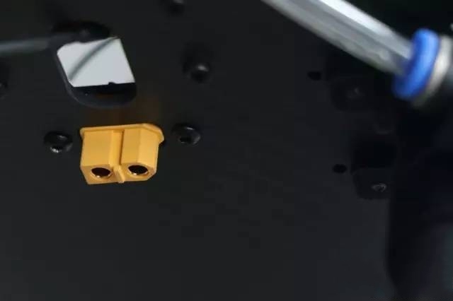
  One of the things to note is that, before installing the rack, it is recommended to weld the power cord plug at the bottom of the center board before the next step in the installation, so as not to facilitate the assembly of the whole machine is not easy to weld the plug at the bottom.


Motor and ESC pre-processing


         As shown in the above figure the whole machine assembly before the main power plug welding and then subsequent assembly of the rack, the installation process is detailed in the following figure:


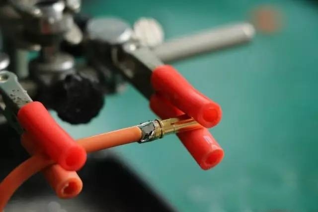
ESC end female connector


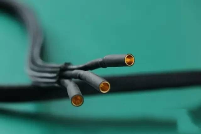
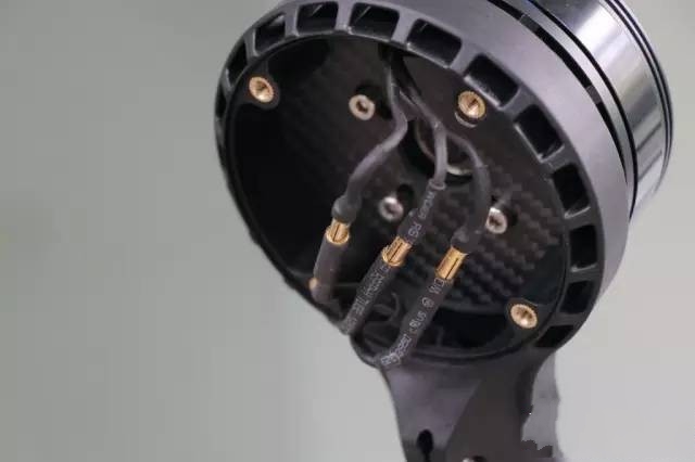
Motor end male connector


         ESC welded plug, cut a section of snakeskin mesh tube will be ESC out of the line sleeve sealed up, and at both ends of the snakeskin mesh tube using 10mm heat-shrinkable tubing shrinkage to avoid bifurcation of the two ends of the snakeskin mesh tube, after the completion of the process is shown in the figure below:


Process the 6 motors and ESCs in turn.


3、install the motor ESC


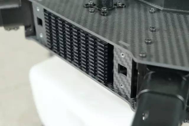
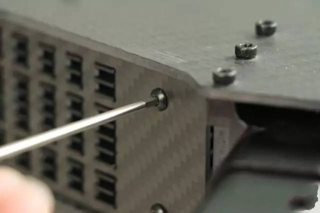
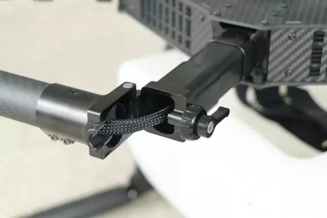
         Motor ESC can be installed into the body after processing, the frame uses a quick release side plate, install ESC will be the side of the four screws unscrewed, remove the side plate, and then the ESC from the side of the body into the side, and then the side plate hollow slot embedded in the ESC fan hot plate re-installed can be used, the power end of the ESC XT90 inserted in the center of the power board of the female end of the control appeared to be the end of the machine through the arm extends to the bottom of the motor base and motor Connected.


Remove the side panel and put in the ESC


 ESC heatsink embedded in side panel slot reattached to body


Outlet wire through the arm


  ESC out to motor out.


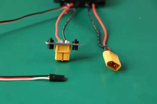
         Solder the step-down ESC output port to an XT60 female adapter plate and the step-down ESC input to an XT60 male connector, as shown below


Soldered XT60 female adapter plate


         Note that the red wire in the middle of the signal wire of the step-down ESC is recommended to be cut off.


         ESC three terminal wires are processed


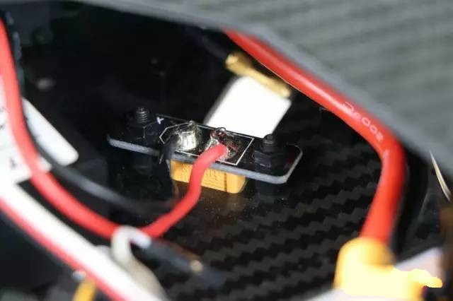
         Attach the adapter plate for the ESC outputs to the side holes in the body panel via nylon posts.


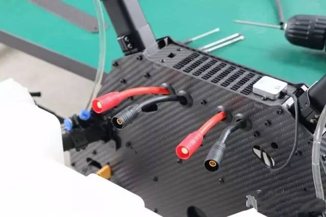
         Fixed after the ESC control output can be exposed to a section in the panel outside, the above control part of the installation is complete.


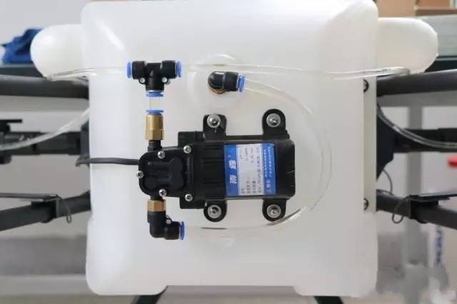
         Then install the water pump, water pipe, nozzle spray part, refer to the following figure, the water pump will be installed to the bottom of the water tank.


         Cut the hose to the proper length for installation.


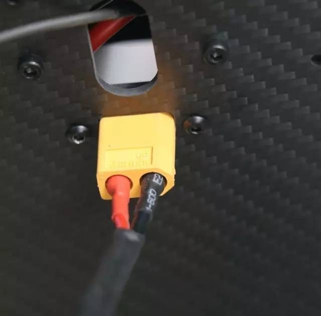
         Extend and solder an XT60 male connector from the pump outlet to the pump controller output at the bottom of the panel.


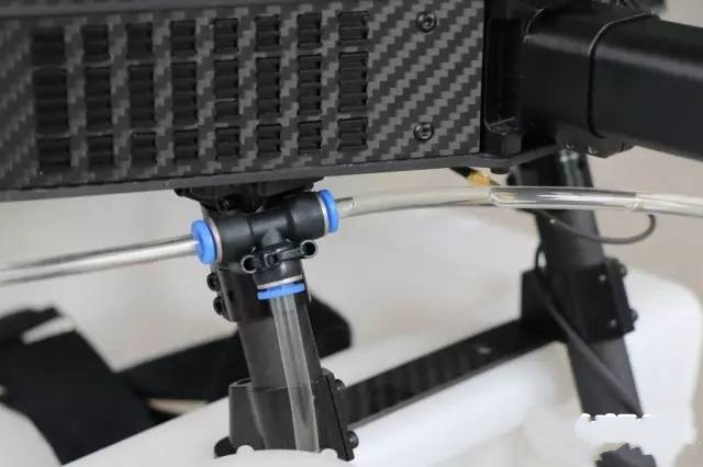
         A two-part adapter at the top of the stand divides the water hose into two directions.


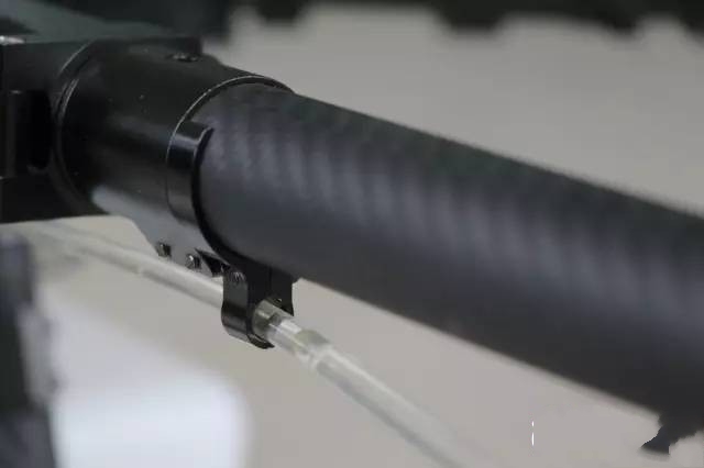
         The water hose extends down the bottom of the arm and under the motor mount, and the water hose can be secured to the arm either with a tie wrap or a more attractive hose clamp (sold separately).


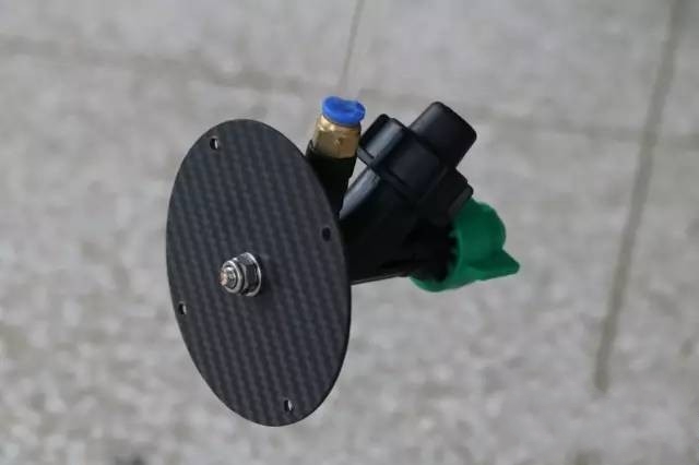
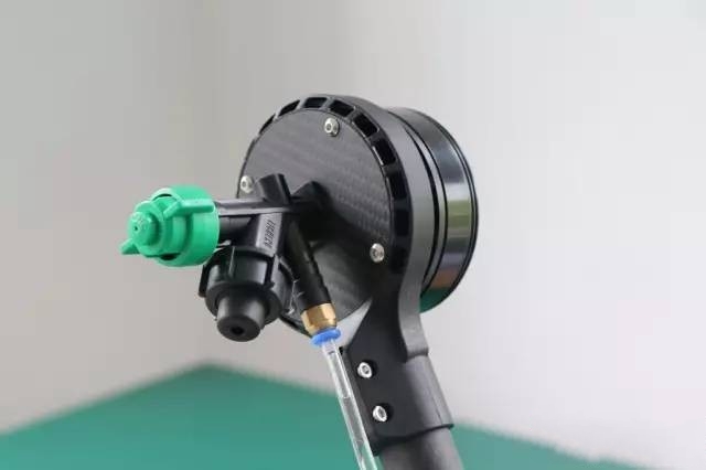
         The nozzle section is fitted to the mounting plate on the bottom of the motor base, tightened using a nut, and finally the base plate is brought up to the bottom of the motor base.


         It is recommended here not to tighten the bottom cover screws until the motor steering has been tested to avoid the need for repeated disassembly during commissioning.


4、Installation of flight control


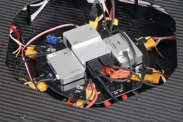
         Flight control we choose DJI A3-AG and Datalink-3 remote control as a reference for installation, detailed wiring and instructions for use refer to the official manual of DJI!


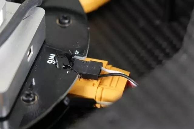
         After installation, it is recommended to apply hot melt glue to the signal cable plug to prevent it from coming loose.


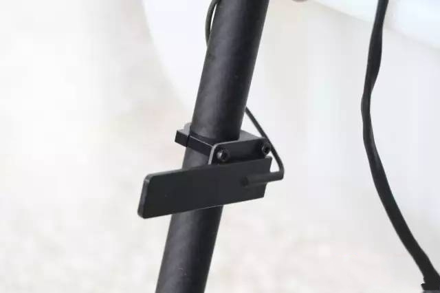
         The Datalink-3 remote control has a very long antenna extension and the end antenna portion is flat, so you can DIY your own mounting plate to fix the antenna vertically on both sides of the stand when installing it.


5、Power on debugging


         After installing the flight control, carefully check whether each line is connected correctly, especially pay attention to whether the positive and negative poles are reversed, whether the signal line and the negative pole are reversed, and whether each socket of the flight control is a corresponding module. After checking whether there is no error, you can power on the debugging.


  Debugging is divided into several points


  The main power supply has two sets of plugs on the left and right sides, when the power is connected to the right side of the negative pole and then the right side of the positive pole, and then connect the left side of the negative pole and the left side of the positive pole.


        Power on momentarily check whether there is any abnormality, whether the indicator light of each module is normal, whether there is any module heating abnormality, confirm that each module works normally before entering the next step


  Remote control and flight control setup, refer to the manual of the flight control and remote control to setup, map the remote control channel, check the forward and reverse direction, and set the basic parameters of the flight control.


  Calibrate the ESC, for ordinary ESCs, make sure to calibrate the travel before flight, for DJI ESCs and some fixed travel ESCs that can't be calibrated, you can skip this step.


  Check and adjust the motor forward and reverse, if the flight control support software test motor through the software test, common flight control, such as DJI, Top Attack, etc., if it does not support by unlocking the view, such as the extreme flight flight control, check if you find that there is motor steering is not correct, through any of the two motors can be reversed by any adjustments to the motor plugs!


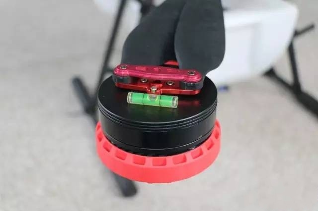
  After the debugging is completed, you can install the nozzle, bottom cover and paddles in order. Use a leveling tape or leveling bubble to correct the level of the motor


Complete installation of the whole machine is completed