In the textile industry, whether it's outdoor tents, marine workwear, automotive interior fabrics, or industrial filter cloths, many textiles must endure prolonged exposure to corrosive environments like salty humid atmospheres and marine moisture. Prolonged exposure to salt spray can cause textiles to fade, lose strength, experience coating peeling, and even compromise functionality and lifespan. Salt spray testing serves as the core assessment method for evaluating the corrosion resistance of such textiles and ensuring product quality.
I. What is Salt Spray Testing?
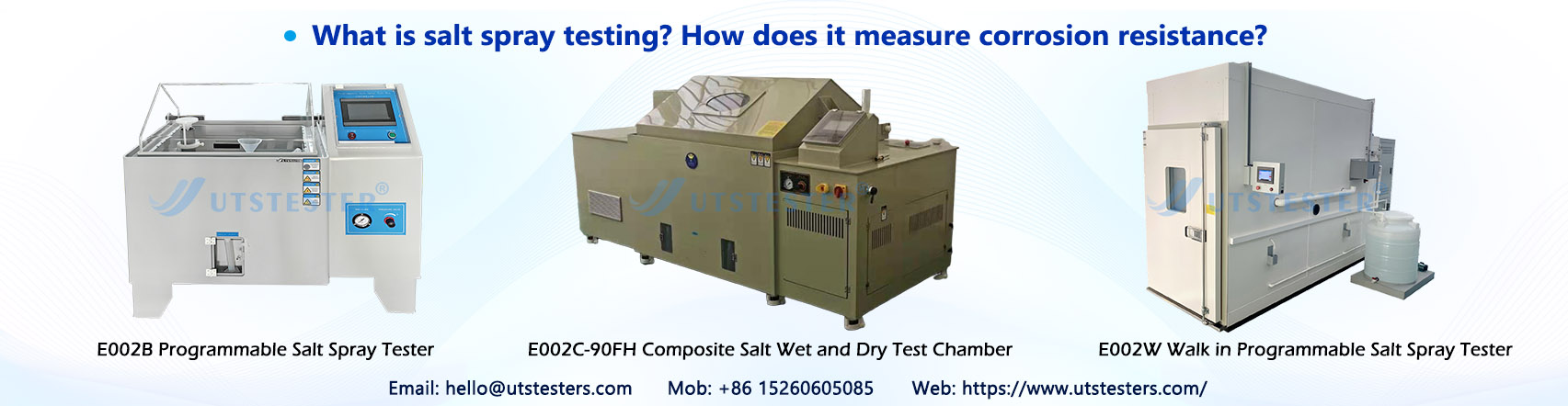
Salt spray testing is fundamentally an accelerated, artificial method for simulating corrosive environments. Using a salt spray tester (salt spray chamber), a controlled salt mist environment is created. Textile samples are placed within this chamber to mimic the erosion process caused by natural salt sprays (such as marine atmospheres or industrial salt-laden dust), thereby rapidly evaluating the corrosion resistance of textiles, their accessories, and coatings.
Compared to natural corrosion testing that can take 1 to several years, salt spray testing accelerates the process by increasing salt solution concentration (typically several to dozens of times higher than natural environments), and precisely controlling parameters like temperature and humidity. This reduces testing cycles to hours or days, efficiently verifying product corrosion resistance while providing reliable data support for textile R&D, quality control, and market access. It addresses the pain points of natural corrosion testing—time-consuming, inefficient, and environmentally uncontrollable.
Tailored to textile industry applications, salt spray testing primarily simulates two core scenarios: First, marine environments, targeting textiles used in coastal regions (e.g., fishing vessels, nets, coastal outdoor apparel) by replicating erosion from high-salinity, high-humidity moisture. Second, industrial environments, simulating the degradation of textiles exposed to corrosive media like salt-laden dust and acidic/alkaline vapors in industrial fabrics (e.g., filter cloths, conveyor belts). This covers various textile materials and products including cotton, polyester, nylon, and coated fabrics.
II. How Does Salt Spray Corrode Textiles?
To grasp the significance of salt spray testing, one must first understand its corrosion mechanism—salt spray does not directly “corrode” fibers but instead degrades textile structure, coatings, and functionality through multiple interactions. This process manifests across three levels, particularly evident in textiles containing metallic accessories or coatings:
1. Indirect corrosion at the fiber level: The primary corrosive agent in salt spray is chloride ions. Their low hydration energy allows easy adsorption onto textile surfaces, penetrating into fiber interiors or interstitial spaces. For natural fibers (e.g., cotton), chloride ions disrupt hydrogen bond structures, causing fiber brittleness and fracture. For synthetic fibers (e.g., polyester, nylon), prolonged salt spray immersion accelerates fiber hydrolysis, reducing tensile and tear strength, and may even cause fiber aging and yellowing.
2. Direct corrosion of accessories and coatings: Commonly used metal accessories (e.g., zippers, buttons, hooks) and coatings (e.g., PU, PVC) on textiles are primary targets for salt spray corrosion. Chloride ions penetrate coatings, disrupting the protective oxide layer on metal surfaces. This creates a micro-battery system involving “low-potential metal—electrolyte solution—high-potential impurities,” leading to rusting of metal accessories, coating blistering, and peeling. Consequently, the overall appearance and durability of textiles are compromised. Simultaneously, acidic salt spray accelerates the separation of coatings from fiber substrates, causing loss of protective functionality.
3. Functional Degradation: Salt residues in the mist clog textile fiber pores, diminishing core functions like breathability and water resistance. For outdoor protective textiles and medical textiles, corrosion may also compromise antimicrobial and safety properties, rendering them unsuitable for intended use.
III. Four Key Steps in Salt Spray Testing
Salt spray testing in the textile industry must adhere to strict standards and procedures to ensure accurate and repeatable results, tailored to the diverse usage scenarios of different textiles. The core process comprises four steps, relying entirely on specialized salt spray testing equipment for precise parameter control:
1. Sample Preparation: Cut standard-sized samples from the textile to be tested (ensuring coverage of critical areas such as fibers, accessories, and coatings). Pre-clean the sample surface to remove oil, dust, and other impurities that could affect corrosion effectiveness. For coated fabrics or textiles with metallic accessories, ensure critical areas are uniformly exposed to salt spray without obstruction or overlap during sample placement. Document sample identification and initial conditions (e.g., appearance, weight, strength).
2. Test Environment Setup: Configure core parameters on the salt spray tester based on the textile's application scenario and relevant standards, as these are critical factors influencing results. Common parameters include: salt solution concentration (typically 5% sodium chloride solution simulating natural salt spray; adjustable for specialized scenarios), pH value (neutral salt spray: 6.5–7.2; acidic salt spray: 3.1–3.3; alkaline salt spray: 8.5–9.5), test temperature (neutral salt spray: 35°C ± 2°C, copper-accelerated acetic acid salt spray: 50°C ± 2°C), salt spray deposition rate (1.5 ml/h ± 0.5 ml/h), and test duration (ranging from 24 hours to hundreds of hours, with outdoor textile tests typically longer). Maintain relative humidity ≥95% inside the chamber to ensure continuous electrolyte film formation on sample surfaces.
3. Sample Placement and Test Operation: Secure prepared samples on the test chamber's sample rack at a 30° angle to the vertical (ensuring uniform salt spray coverage). Close the chamber and activate the instrument to commence testing. During testing, the instrument must maintain continuous, stable spraying with constant parameters, avoiding fluctuations in temperature or salt spray concentration. Assign dedicated personnel to monitor the equipment, conducting regular checks to ensure compliance with standards and prevent invalid data.
4. Post-Test Handling and Observation: After testing concludes, remove the samples and gently rinse residual salt from the surface with clean water (avoid vigorous wiping that could damage the samples). Place them in a drying oven until constant weight is achieved. Compare the samples' pre- and post-test conditions, record corrosion-related data to provide a basis for subsequent corrosion resistance evaluation, and compile the test data into a comprehensive inspection report.
IV. How Does Salt Spray Testing Measure Corrosion Resistance?
Salt spray testing evaluates a textile's corrosion resistance by comparing sample changes before and after testing. Combining qualitative observation with quantitative analysis, it provides a comprehensive assessment across multiple dimensions. Evaluation priorities vary slightly for different textiles and can be categorized into five dimensions:
(1) Qualitative Assessment: Visual Inspection of Corrosion Appearance
This is the most fundamental and direct assessment method, primarily observing corrosion phenomena on the sample surface. Industry standards are used to determine corrosion resistance grades, focusing on three key aspects:
1. Fibers and Fabrics: Check for yellowing, brittleness, breakage, fading, pilling, or fuzzing. No significant changes indicate excellent corrosion resistance.
2. Metal accessories: Check for rust spots, rust stains, or oxidation discoloration. Absence of any corrosion marks is optimal; minor rust spots require standard-based qualification assessment.
3. Coating-to-accessory bonding: Inspect for coating blistering, peeling, or cracking. Verify secure attachment of accessories to fabric (e.g., zipper jamming, button detachment). Complete coating integrity and firm connections indicate corrosion resistance compliance.
(2) Quantitative Assessment: Precise Corrosion Severity Measurement
Qualitative observation cannot accurately distinguish subtle differences. For mid-to-high-end textiles (e.g., premium outdoor apparel, aerospace textiles, military textiles), quantitative testing using specialized instruments is required. This assessment centers on six key metrics, which also serve as the core evaluation criteria for textile salt spray testing:
1. Weight Change Rate: Weigh samples before and after testing using precision electronic balances to calculate percentage weight gain/loss. Weight gain typically indicates corrosion product adhesion, while loss suggests fiber or coating corrosion. A lower change rate indicates superior corrosion resistance.
2. Strength Retention Rate: Measured by testing tensile strength and tear strength before and after exposure using a tensile testing machine. The retention rate indicates the proportion of strength preserved—higher retention signifies minimal fiber corrosion and superior corrosion resistance.
3. Color Difference Change: Measure the ΔE value (color difference) of the textile before and after testing using a color difference meter to evaluate fading and discoloration levels. A lower ΔE value indicates better color stability. Decorative textiles and apparel fabrics typically require ΔE ≤ 2.0, meaning no noticeable color difference to the naked eye.
4. Coating Adhesion: For coated textiles, determine the bond strength between coating and substrate using the cross-hatch adhesion test or tensile adhesion test to evaluate adhesion grades. This prevents coating peeling, with Grade 1 adhesion (no peeling) being optimal.
5. Corrosion Area Ratio: Using a 10-level rating system, assess the grade based on the percentage of surface defects (corrosion, blistering, fading) on the sample. Higher grades indicate better corrosion resistance—Grade 10 has no defects, while Grade 1 has over 25% corrosion area.
6. Microstructure and Functionality: Observe corrosion morphology (e.g., cracks, blistering) on textile surfaces using optical or scanning electron microscopes to analyze fiber structural changes. Simultaneously evaluate functional indicators like waterproofing, breathability, and antimicrobial properties to ensure post-corrosion performance meets usage requirements—a core assessment focus for outdoor and medical textiles.
V. Four Major Types of Salt Spray Tests
1. Neutral Salt Spray Test (NSS): The most commonly used type, simulating ordinary marine atmospheres and humid, saline environments. The salt solution has a pH of 6.5-7.2 and a temperature of 35°C ± 2°C. A 24-hour test is equivalent to approximately one year of corrosion in natural environments. Suitable for general outdoor textiles, home textiles, cotton-polyester blended fabrics, etc., it is the most widely applied basic test type in the textile industry.
2. Acetic Acid Salt Spray Test (AASS): An acidic environment test with a salt solution pH of 3.1–3.3 and a temperature of 35°C ± 2°C. A 24-hour test is equivalent to approximately 3 years of natural corrosion. Suitable for textiles containing copper-nickel-chromium accessories or aluminum anodized films (e.g., high-end garment zippers, bathroom textiles). Its corrosion efficiency is 2–3 times that of neutral salt spray.
3. Copper-Accelerated Acetic Acid Salt Spray Test (CASS): High-intensity corrosion test. Copper chloride is added to the acidic salt spray, with temperature increased to 50°C ± 2°C. A 24-hour test corresponds to approximately 8 years of natural environmental corrosion. Suitable for high-end textiles and precision accessories (e.g., aerospace textiles, premium hardware accessories). Corrosion efficiency is 5-8 times that of neutral salt spray, enabling rapid differentiation of product quality grades.
4. Alternating Salt Spray Test: Simulates complex natural environments (salt spray, drying, humid heat cycles). 35°C salt spray exposure alternates with ambient temperature drying and humid heat phases, closely mimicking long-term outdoor use. Suitable for photovoltaic textiles, marine textiles, outdoor tents, etc.
VI. Significance of Salt Spray Testing
For textile enterprises, salt spray testing transcends mere “compliance verification.” It serves as a critical component for enhancing product competitiveness and mitigating quality risks, with its core value manifested in three key areas:
1. Identifying vulnerabilities in textiles exposed to corrosive environments (e.g., rust-prone accessories, coating peeling) through testing enables timely optimization of material selection and production processes. This prevents post-market quality issues, reducing after-sales complaints and rework costs;
2. During new product development, salt spray testing enables comparative analysis of corrosion resistance across different materials and processes. This facilitates optimization of product formulations and structures, creating more durable textiles suited for complex scenarios (e.g., high-end outdoor apparel, long-lasting industrial filter fabrics) and fostering differentiated competitive advantages.
3. Whether for domestic sales or export, many textiles (e.g., outdoor gear, automotive interior fabrics, military textiles) require salt spray test compliance reports. Passing these tests ensures regulatory compliance while precise test data provides robust support for product promotion, enhancing customer trust.
Email: hello@utstesters.com
Direct: + 86 152 6060 5085
Tel: +86-596-7686689
Web: www.utstesters.com


, or Sealed (RS/2RS) Bearings?")


